Apparatus and method for analyzing an electro-acoustic system

an electro-acoustic system and apparatus technology, applied in the direction of electrical apparatus, stereophonic arrangments, loudspeaker spatial/constructional arrangements, etc., can solve the problems of a single loudspeaker not being able to accurately reproduce sound over the entire frequency rang

Inactive Publication Date: 2005-11-29
ELECTRONICS ENG & MFG
View PDF10 Cites 37 Cited by
  • Summary
  • Abstract
  • Description
  • Claims
  • Application Information

AI Technical Summary

Problems solved by technology

Consequently, the performance of an electro-acoustic system may be severely limited by its loudspeakers.
It is difficult for a single loudspeaker to accurately reproduce sound over the entire frequency range.
However, electro-acoustic systems having multiple loudspeakers pose a particular challenge to the audio engineer.
In the case where the multiple loudspeakers are physically disassociated and may be placed at different positions throughout the listening area, the issue of time coherency between the audio signal generated by each loudspeaker becomes particularly significant.
It is quite often the case where the poor quality of sound is not due to the quality of the loudspeaker itself, but is a result of the multiple loudspeakers not being aligned in time effectively for the majority of the audience.
Practically speaking, it is often not possible to physically position multiple loudspeakers in relation to one another to produce a coherent wavefront.
The positioning of loudspeakers may be limited by the physical space available for placement of the loudspeakers, as well as the size and shape of the listening area in which the loudspeakers are placed.
However, this method does not acknowledge the fact that the distance of each loudspeaker should be measured from its respective “acoustic center.” The acoustic center of a loudspeaker is a term used to note the actual sonic origin of sound from the loudspeaker.
Further complicating the measurement is the fact that the acoustic center of a loudspeaker is frequency dependent.
Another factor that should be considered, but cannot be determined from physical measurement, is additional delay introduced by the electro-acoustic system itself, for example, digital signal processing of the stimulus signal prior to providing the resulting analog signal to the loudspeakers.
Consequently, the resulting audio signals may destructively interfere with one another and affect the overall sound quality.
Determining the polarity of a particular loudspeaker by visually inspecting its connection to the power amplifier may not be practical if the loudspeaker is located in a position that is difficult to reach.
In either case, visually inspecting the connection of the loudspeaker will not be easy.
Furthermore, the existing analysis equipment often involve complicated and time-consuming setup procedures, which may also be carried out only by specially trained technicians.

Method used


Image

  • Apparatus and method for analyzing an electro-acoustic system
  • Apparatus and method for analyzing an electro-acoustic system
  • Apparatus and method for analyzing an electro-acoustic system

Examples


Embodiment Construction

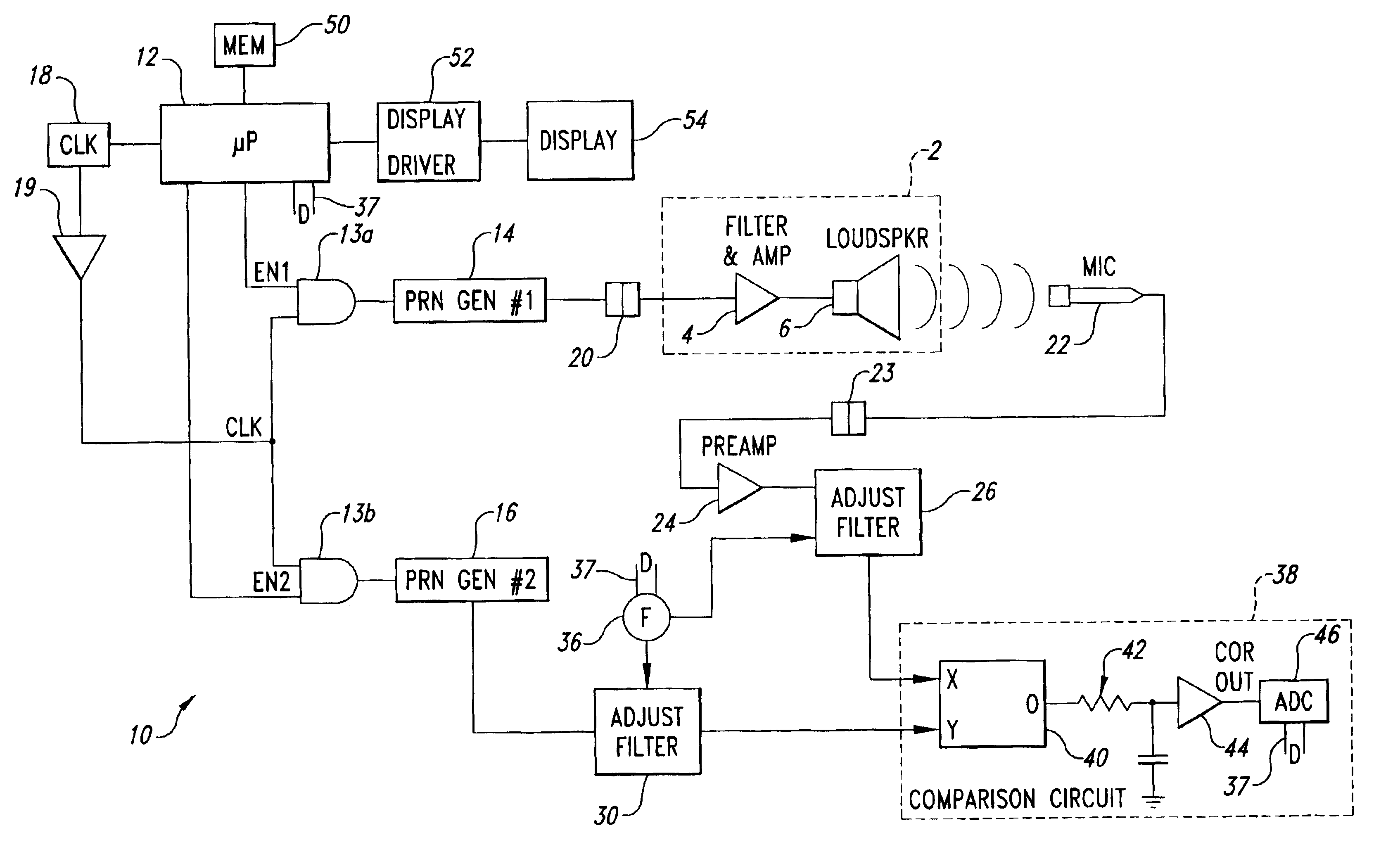
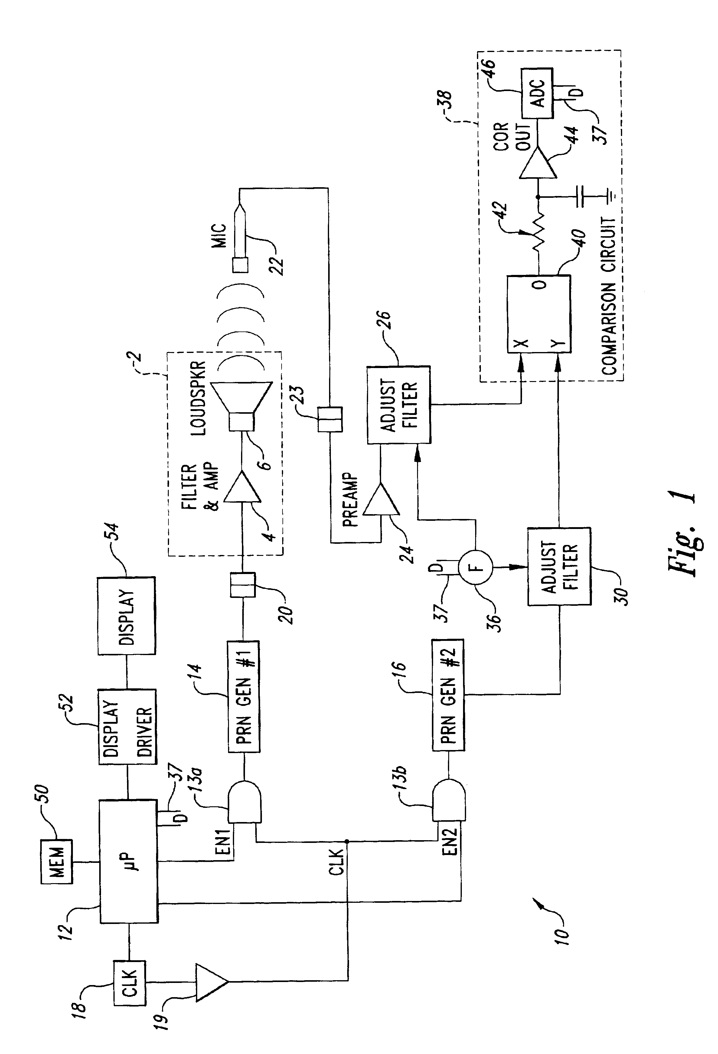
[0014]Shown in FIG. 1 is an analysis system 10 according to an embodiment of the present invention. The analysis system 10 is coupled to a conventional electro-acoustic system 2, having a power amplifier 4 and an electro-acoustic transducer 6, such as an audio loudspeaker. The analysis system 10 measures the delay time for a stimulus signal applied to the electro-acoustic system 2 to be detected at a measurement point. The delay time is in turn used by the analysis system 10 to calculate the distance between the transducer 6 and the measurement point for a particular measurement frequency. The analysis system 10 may be programmed to automatically perform the measurement, or the measurement may be manually performed by an operator.

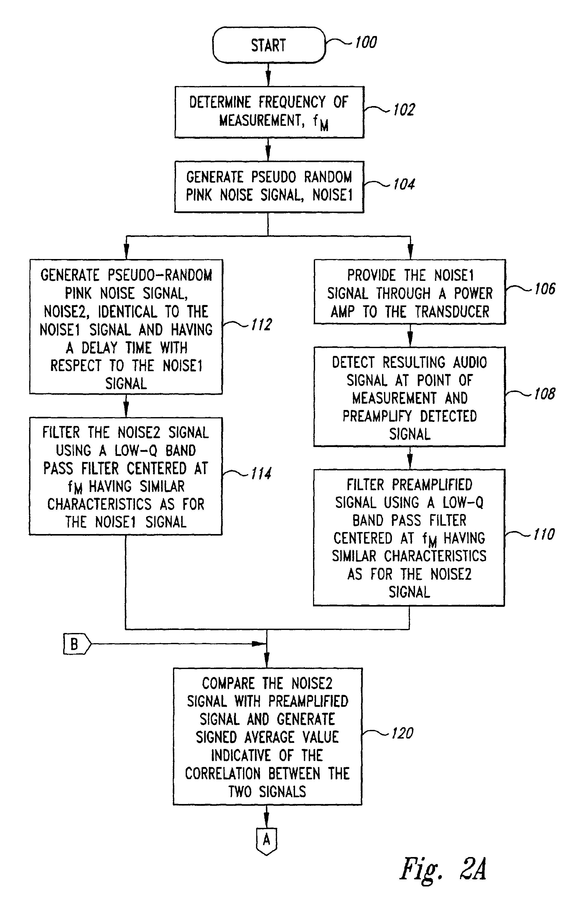
[0015]Various signals may be used for the stimulus signal. Generally, the stimulus signal should have unique characteristics so that a delay time may be determined from correlating the audio signal generated in response to the stimulus signal with a delayed...


PUM


Abstract

An analysis system for accurately measuring the time-of-flight of an audio signal generated in response to a stimulus signal by an electro-acoustic transducer of an electro-acoustic system, such as an audio loudspeaker, to a point of measurement. The measurement is made by correlating the audio signal to a second signal having the same characteristics as the stimulus signal, but is delayed with respect to the stimulus signal. The measurement identifies the total overall delay from the time the stimulus signal is generated to the time the resulting audio signal is detected. Thus, any system delays, such as those due to signal processing, have already been accounted for by the measurement. Some or all of the measurement process may be automated through software programming in order to minimize measurement time. The time-of-flight is the delay time corresponding to when the stimulus signal, or the delayed second signal, and the resulting audio signal reach peak correlation. The distance of the acoustic center of the transducer can be calculated from the measured time-of-flight. The resulting comparison between the audio signal and the delayed second signal may also be used to determine the polarity of the transducer with respect to the stimulus signal.

Description

TECHNICAL FIELD[0001]The present invention relates generally to audio test equipment, and more particularly, to a system and method for analyzing the distance of the acoustic center of an acoustic transducer and its polarity.BACKGROUND OF THE INVENTION[0002]Acoustic transducers of a conventional electro-acoustic system, such as loudspeakers, play a fundamental and significant role in an audience's listening experience. The loudspeakers are, in fact, the critical link between the electrical signal representing audio information and the resulting audio signal heard by the listener. Consequently, the performance of an electro-acoustic system may be severely limited by its loudspeakers. The loudspeakers of an electro-acoustic system must reproduce sound throughout the audio spectrum, which is typically considered to be from 20 Hz to 20,000 Hz. It is difficult for a single loudspeaker to accurately reproduce sound over the entire frequency range. Several loudspeakers are typically used i...

Claims


Application Information

Patent Timeline
Patent Type & Authority Patents(United States)
IPC IPC(8): H04R29/00
CPCH04R29/00
Inventor FREEMAN, DWIGHT H.GRIFFITHS, DENNIS LYNN
Owner ELECTRONICS ENG & MFG
Why Eureka
Try Eureka