Integration of a field device in an installation control system

a field device and installation control technology, applied in the field of installation control engineering, can solve the problems of large amount of manual effort, increased commissioning effort and failures during operation, risky retrospective correction of installation, etc., and achieves the effect of reducing commissioning effort, saving a large amount of engineering effort, and improving the quality of the resulting installation control system

Inactive Publication Date: 2005-11-29
ABB RES LTD
View PDF22 Cites 64 Cited by
  • Summary
  • Abstract
  • Description
  • Claims
  • Application Information

AI Technical Summary

Benefits of technology

[0017]One advantage of the invention is thus that no detailed logic links and communications parameters need be specified by hand, thus saving a large amount of effort in engineering. A further advantage is that a significant proportion of the engineering does not take place until physical installation and commissioning and that there is therefore no need to develop and store a consistent, system-wide description of all the communications links in advance. A further advantage is that there is thus no need to exchange relatively large amounts of data between different engineering tools for configuration of field devices and the control station. Furthermore, no mechanisms are required to ensure consistency of such data, and the majority of errors resulting from inconsistent data are eliminated. This reduces the effort for commissioning and improves the quality of a resulting installation control system.
[0018]In a first preferred variant of the invention, the control station does not actually contain any information about a structure of the installation before physical installation. During the physical installation of a field device, a graphics equivalent or representation, for example, of the field device is produced in the control station. Using a number of such equivalents, an operator manually produces a representation of the structure of the installation on the control station.
[0019]In a second preferred variant of the invention, the control station contains informat...

Problems solved by technology

Despite the use of special development tools, a large amount of manual effort is, however, required for specification of the links and interactions between functions during planning and commissioning.
Owing to the manual...

Method used


Image

  • Integration of a field device in an installation control system
  • Integration of a field device in an installation control system
  • Integration of a field device in an installation control system

Examples


Embodiment Construction

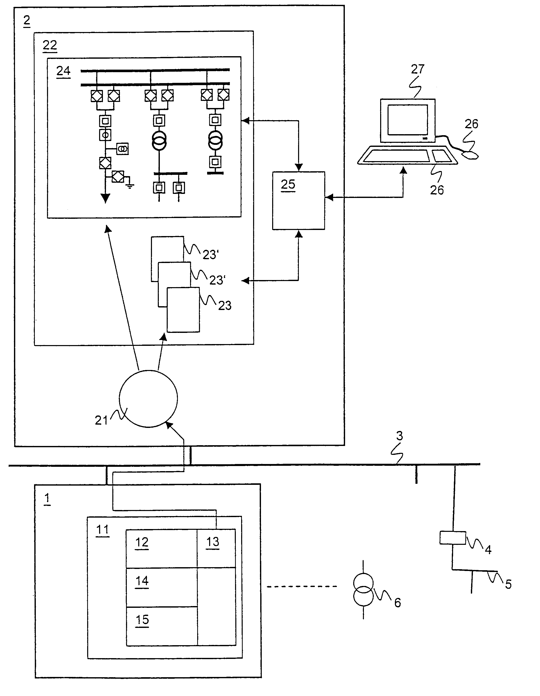
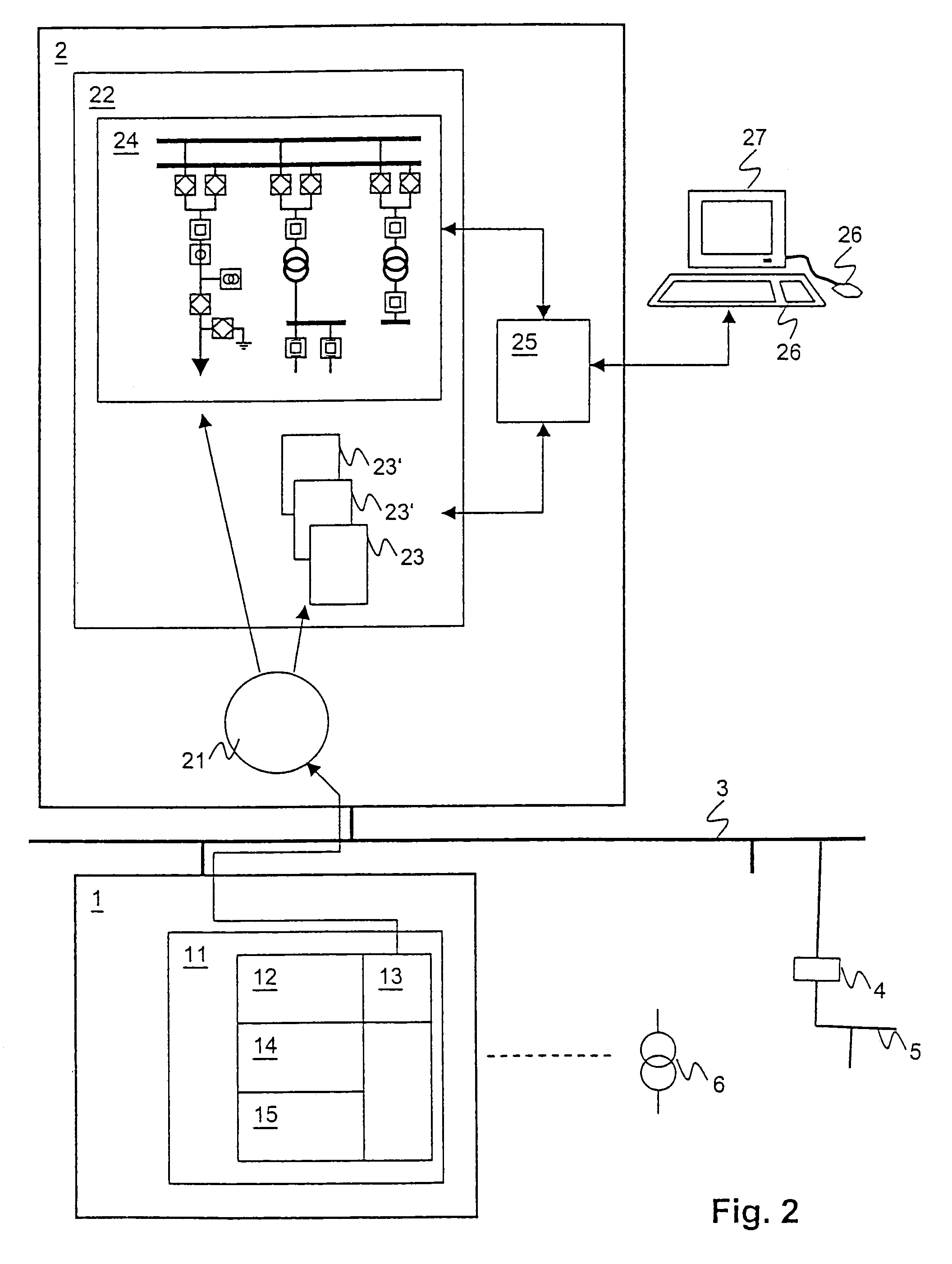
[0031]FIG. 2 shows a structure of a system according to the invention, schematically. One or more field devices 1 are connected to at least one control station 2 via a communications network which is formed from one or more communications buses 3,5 and bus couplers 4.

[0032]Field devices 1 are control engineering or secondary units. They are used for controlling, regulating and protecting a primary unit 6. Primary units 6 are units which carry out an actual function of an installation, for example circuit breakers, isolators, overhead lines, transformers, generators, motors, turbines, pumps etc.

[0033]At least one device function 11 is stored and can be carried out in a field device 1. The device function 11 comprises an external interface 12 for communication with other control engineering units, algorithms 14 for controlling, regulating, monitoring and protecting the primary unit 6, and an internal interface 15 for driving the primary unit 6. According to the invention, the device f...


PUM


Abstract

A method and a system for integration of a field device in an installation control system having a communications network and a control station functions in that a field device transmits a functional description of device functions to the control station in a standardized form, whereupon functions associated with the field device are installed on the control station, and communications links are set up between the device functions of the field device and the functions of the control station. In one preferred version of the invention, device functions are automatically or manually combined with an installation structure. The invention is preferably used with high voltage or medium voltage switchgear assemblies and leads to a considerable reduction in the complexity for specification and commissioning of installation internal communications links and to higher quality of a resulting installation control system.

Description

FIELD OF THE INVENTION[0001]The invention relates to the field of installation control engineering, in particular substation control engineering for high-voltage, medium-voltage or low-voltage substations or switchgear assemblies. It relates to a method and a system for integration of a field device in an installation control system.BACKGROUND OF THE INVENTION[0002]An installation, in particular a high-voltage or medium-voltage substation, is controlled by a distributed installation control system from field devices which are connected to one another via communications buses. FIG. 1 shows, schematically, a structure of an installation control system having field devices 1, a control station 2, a first and a second communications bus 3, 5 and a bus coupler 4. The field devices 1 control, regulate, monitor and protect primary units 6 in the installation which carry out the installation's actual purpose. Primary units 6 are, for example, switches, drives, generators or transformers. Th...

Claims


Application Information

Patent Timeline
IPC IPC(8): G05B15/02G05B19/418G06F13/00
CPCG05B19/4185Y02P90/02
Inventor PREISS, OTTODER MAUER, DOMINIK AUF
Owner ABB RES LTD
Why Eureka
Try Eureka