Micro coaxial connector

a coaxial connector and micro-coaxial technology, applied in the direction of coupling device details, coupling device connection, two-pole connection, etc., can solve the problems of inability to meet the needs of customers, limited production output with instable quality, and defective products, etc., to shorten the manufacturing time and increase the production output

Inactive Publication Date: 2005-12-06
SPEED TECH
View PDF4 Cites 73 Cited by
  • Summary
  • Abstract
  • Description
  • Claims
  • Application Information

AI Technical Summary

Benefits of technology

[0009]It is an object of the invention to provide a micro coaxial connector having a design of a pair of tag-shaped bending arms downwardly extended at two sides of a signal terminal thereof, respectively, wherein the bending arms ...

Problems solved by technology

1. In the two prior U.S. patents, the terminals are connected to the coaxial cable by means of soldering. However, soldering is likely to leave behind residual objects such as tin dregs, which further affect performances of electrical characteristics of products. In addition, manual soldering is not only time-consuming but also labor-intensive, and production out...

Method used


Image

  • Micro coaxial connector
  • Micro coaxial connector
  • Micro coaxial connector

Examples


Embodiment Construction

[0017]These and other objects of the present invention will become apparent from a reading of the following specification, taken in conjunction with the enclosed drawings.

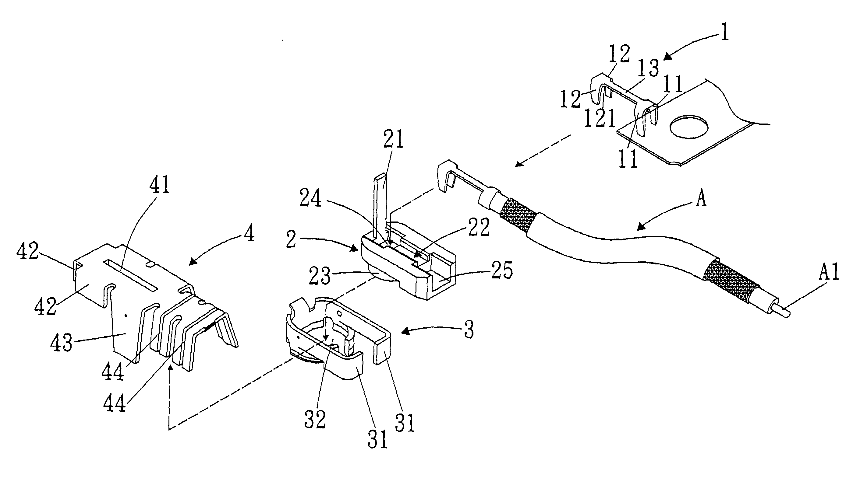
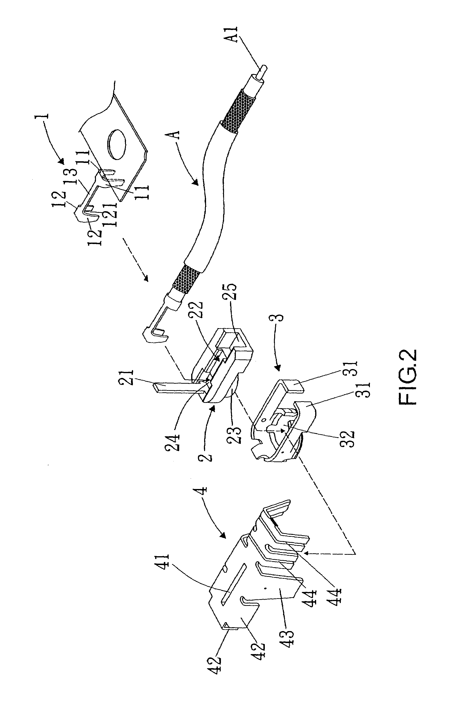
[0018]Referring to FIG. 2 showing an exploded elevational view according to the invention, the invention comprises:[0019]a signal terminal 1 being long and thin in shape; and formed with a pair of downwardly extended contact arms 12 and bending arms 11 at front and rear ends thereof, respectively, and a strip portion 13 at a middle section therebetween; wherein:[0020]the contact arms 12 are for contacting with a base of a printed circuit board (PCB), and the two bending arms 11 are formed with a clamping aperture 111 in between for accommodating a central conductor A1 of a coaxial cable A as well as clamp and position the coaxial cable A;[0021]a main body 2 made of an electrically insulating material has a cylindrical protruding portion 23 at a front portion thereof, a pressing tag 21 at a front end thereof, a dent...


PUM


Abstract

The micro coaxial connector includes a signal terminal, a main body, and two grounding elements. The signal terminal has a pair of tag-like contact arms and bending arms at a front and rear end thereof, and a strip plane at a middle section thereof. The contact arms are for contacting with a base of a printed circuit board (PCB). The main body is for receiving the signal terminal and serving as an insulation. The two grounding elements are separated designs. The cylindrical-shaped first grounding element is for receiving and fastening the main body, and has a pair of extension arms for providing the coaxial cable with suitable clamping forces. The second grounding element is a cover-like body, and has a strip-like projection for increasing strength against bending of the second grounding element and preventing loosening of components.

Description

BACKGROUND OF THE INVENTION[0001](a) Field of the Invention[0002]The invention relates to a micro coaxial connector, and more particularly, to a micro coaxial connector having elevated quality yielding rate and production output as well as enhanced electrical characteristics, thereby uplifting economical values thereof.[0003](b) Description of the Prior Art[0004]The invention provides an advanced micro coaxial connector in connection with the U.S. Pat. No. 6,508,668B1, and 6,503,100B2.[0005]Referring to the U.S. Pat. No. 6,508,668B1, and 6,503,100B2, and FIG. 1, the prior invention comprises terminals 10, a dielectric block 20 and an outer conductor 30. The terminals 10 are U-shaped bodies, and are made from metal strips so as to be coupled with a carrier 11 at regular intervals. Each terminal 10 has a connection section 12 and a contact section 13. A front end of each terminal 10 has a separated line 14 for pressing against a cover section 22 of the dielectric block 20. A rear end ...

Claims


Application Information

Patent Timeline
IPC IPC(8): H01R9/05H01R13/56H01R13/646
CPCH01R9/0518H01R13/567H01R24/40H01R2103/00
Inventor CHU, CHANG-HSING
Owner SPEED TECH
Why Eureka
Try Eureka