
Battery pack and battery remaining power calculating method

a battery pack and remaining power technology, applied in secondary cells, cell components, instruments, etc., can solve the problems of increasing internal impedance, slow reduction of electric current flowing during charging operation, and requiring a long charging tim

Inactive Publication Date: 2005-12-06
SONY CORP
View PDF9 Cites 8 Cited by
  • Summary
  • Abstract
  • Description
  • Claims
  • Application Information

AI Technical Summary

Benefits of technology

[0021]It is an object of the present invention to provide a new battery pack and a method for calculating the remaining capacity of a battery that can solve the above-described problems of a usual battery pack.
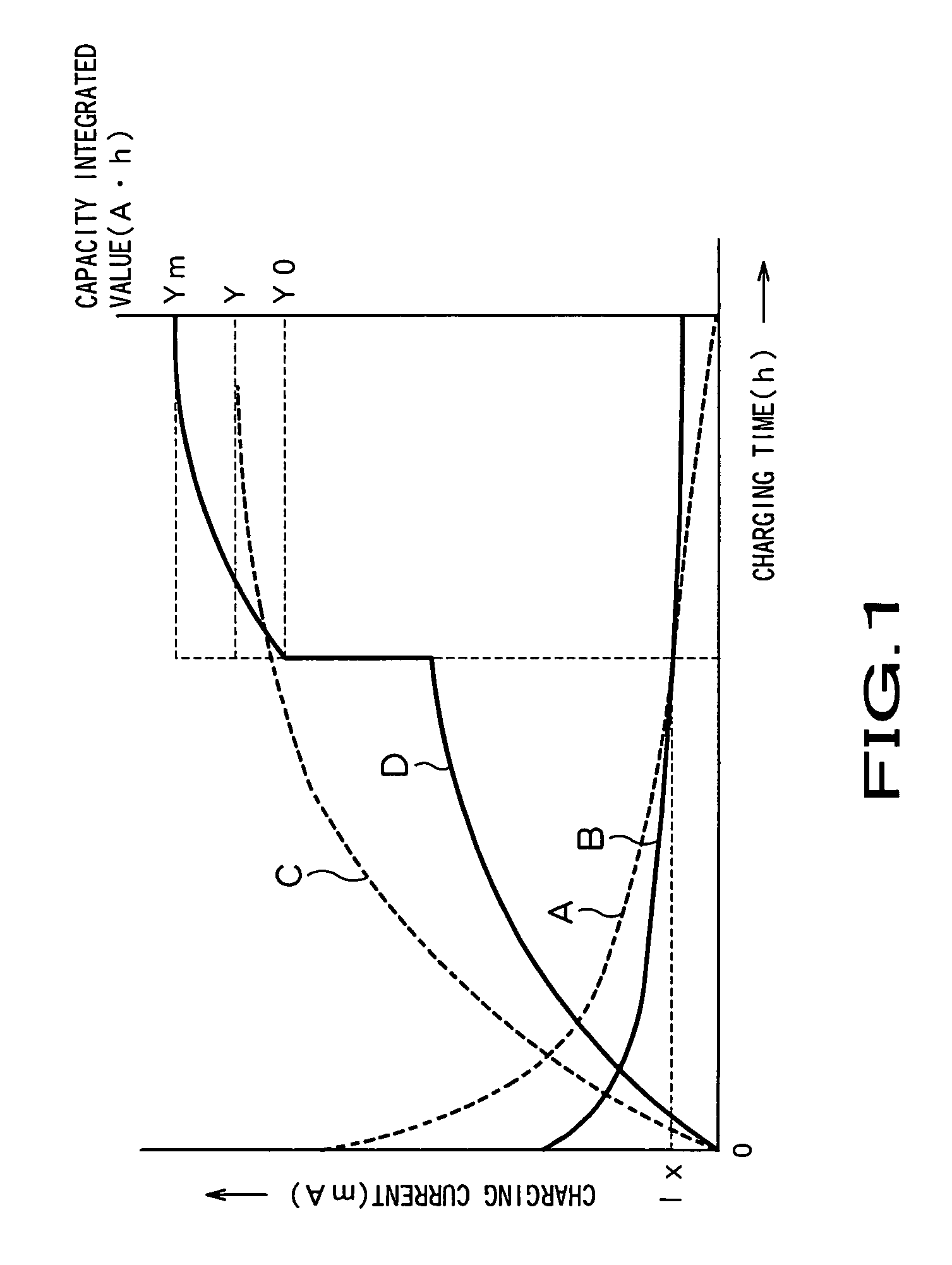
[0023]As the deterioration of a battery pack using a battery cell that can be charged is progresses, internal impedance is increased. Accordingly, when a new battery pack undergoes a constant voltage charging operation, since the internal impedance is low, much electric current is allowed to flow upon start of charging operation, a quantity of electric current flowing during the charging operation is rapidly decreased and the battery pack is completely charged for a short charging time (h1). On the other hand, when a deteriorated battery pack undergoes a constant voltage charging operation, since the internal impedance is high, a small quantity of electric current flows upon start of charging operation and the quantity of electric current flowing during the charging operation is slowly decreased to require a long charging time (h2).

Problems solved by technology

As the deterioration of a battery pack using a battery cell that can be charged is progresses, internal impedance is increased.
On the other hand, when a deteriorated battery pack undergoes a constant voltage charging operation, since the internal impedance is high, a small quantity of electric current flows upon start of charging operation and the quantity of electric current flowing during the charging operation is slowly decreased to require a long charging time (h2).

Method used


Image

  • Battery pack and battery remaining power calculating method
  • Battery pack and battery remaining power calculating method
  • Battery pack and battery remaining power calculating method

Examples


Embodiment Construction

[0041]Now, a battery pack and a method for calculating a remaining capacity of a battery according to the present invention will be described in detail.

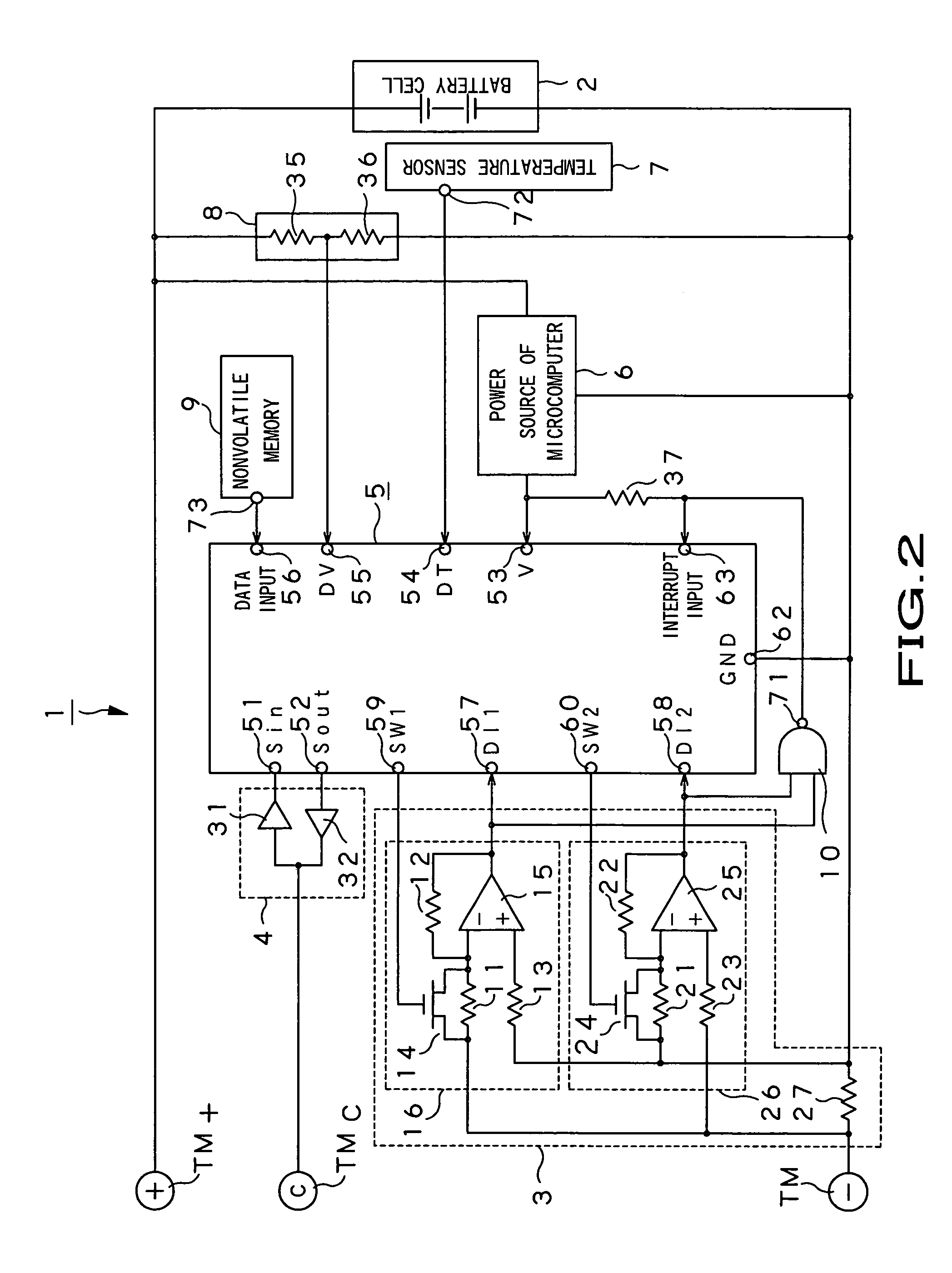
[0042]A battery pack 1 according to the present invention comprises, as shown in FIG. 2, a battery cell 2 that is charged and discharged, a charging and discharging current detecting circuit 3 for detecting electric current for charging and discharging the battery cell 2, a communication circuit 4, a microcomputer 5, a power source 6 of a microcomputer, a temperature sensor 7, a voltage detecting circuit 8, a nonvolatile memory 9 and a two input NAND gate 10.

[0043]The battery pack 1 is connected to or incorporated in an electronic device such as a video camera, a portable telephone or a personal computer and used as a power source of the electronic device.

[0044]In the battery pack 1 according to the present invention, a cathode of the battery cell 2 is connected to a plus terminal TM+ of the battery pack 1 and an anode of the battery...


PUM


Abstract

The present invention relates to a battery pack having a function for calculating a remaining capacity of a battery cell that can be charged. When a calculated capacity integrated value Y is smaller than a maximum capacity integrated value Ym, a microcomputer (5) incorporated in the battery pack determines the capacity integrated value Y as the remaining capacity data of a battery. When the calculated capacity integrated value Y is the maximum capacity integrated value Ym or larger, the microcomputer determines the maximum capacity integrated value Ym as the remaining capacity data of the battery. Further, the microcomputer (5) corrects a reference capacity integrated value Y0 on the basis of the number of times that the capacity integrated value Y reaches the maximum capacity integrated value Ym.

Description

TECHNICAL FIELD[0001]The present invention relates to a battery pack used as a power source of an electronic device such as a video camera, a portable telephone or a personal computer and a method for calculating the remaining capacity of a battery in the battery pack.[0002]This application claims a priority based on Japanese Patent Application No. 2002-171828 filed in Jun. 12, 2002 in Japan and Japanese Patent Application No. 2002-242650 filed in Aug. 22, 2002 in Japan. These applications are applied to this application by referring to them.BACKGROUND ART[0003]A battery pack having a battery cell as a secondary battery capable of charging such as a lithium-ion battery, an NiCd battery, a nickel hydrogen battery, etc. has been hitherto employed. Such a kind of battery pack is used as a power source of an electronic device such as a video camera, a portable telephone, or a personal computer or the like.[0004]In the battery pack used as the power source of the electronic device, for i...

Claims


Application Information

Patent Timeline
IPC IPC(8): H01M10/44H01M10/46H02J7/00
CPCH01M10/44Y02E60/10H01M10/486H01M10/443H01M50/574H01M50/581H01M50/569
Inventor TSUCHIYA, YUKIOSATO, HIDEYUKITASHIRO, KEI
Owner SONY CORP
Learn More