Near-field magneto-optical microscope

a magneto-optical microscope and near-field technology, applied in the direction of scanning probe techniques, magnetic field measurement using permanent magnets, instruments, etc., can solve the problems of difficult image interpretation and unsuitable practical approach

Inactive Publication Date: 2005-12-06
THE UNITED STATES AS REPRESENTED BY THE DEPARTMENT OF ENERGY
View PDF2 Cites 10 Cited by
  • Summary
  • Abstract
  • Description
  • Claims
  • Application Information

AI Technical Summary

Problems solved by technology

However, the signal carrying the magnetic information is superimposed on a large background, and therefore this configuration is not suitable as a practical approach.
In addition, the interpretation of the images is difficult since they depend sensitively on the alignment of illumination, sample surface and aperture.

Method used


Image

  • Near-field magneto-optical microscope
  • Near-field magneto-optical microscope

Examples


Embodiment Construction

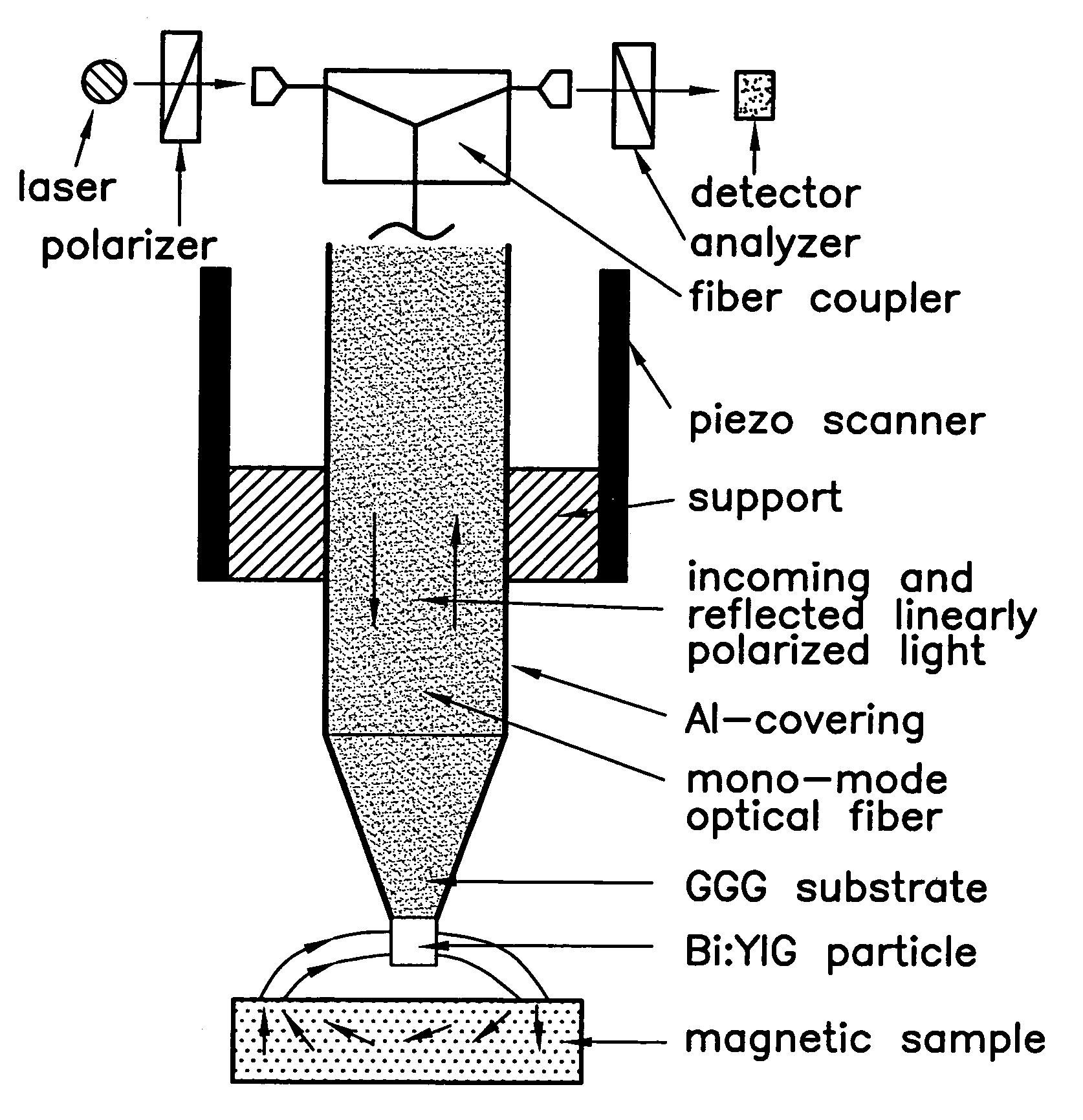
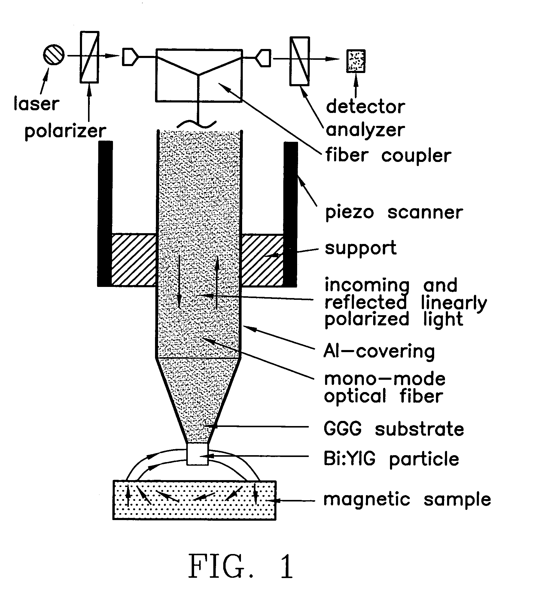
[0012]Referring to FIG. 1, the basic design of the near-field magneto-optical microscope is shown. The external optical components used for light generation, guidance and detection are shown schematically near the top of the figure. The magnetic fields generated by the sample are probed through the magneto-optical response of the special multi-functional tip. It consists of a gadolinium-gallium-garnet (GGG) substrate which carries a Bi or Ce doped rare-earth garnet particle. The interface between the GGG substrate and doped rare-earth garnet particle defines the optical aperture while the garnet particle provides very high magneto-optical activity including magnetic dichroism, and linear and circular magnetic birefringence. Incident linearly polarized light is transmitted first through the fiber, then through the GGG substrate defining the aperture and then scattered back by the garnet particle. The light travels back through the fiber and is analyzed with a polarization filter and ...


PUM


Abstract

A device and method for mapping magnetic fields of a sample at a resolution less than the wavelength of light without altering the magnetic field of the sample is disclosed. A device having a tapered end portion with a magneto-optically active particle positioned at the distal end thereof in communication with a fiber optic for transferring incoming linearly polarized light from a source thereof to the particle and for transferring reflected light from the particle is provided. The fiber optic has a reflective material trapping light within the fiber optic and in communication with a light detector for determining the polarization of light reflected from the particle as a function of the strength and direction of the magnetic field of the sample. Linearly polarized light from the source thereof transferred to the particle positioned proximate the sample is affected by the magnetic field of the sample sensed by the particle such that the difference in polarization of light entering and leaving the particle is due to the magnetic field of the sample. Relative movement between the particle and sample enables mapping.

Description

CONTRACTUAL ORIGIN OF THE INVENTION[0001]The United States Government has rights in this invention pursuant to Agreement between Argonne National Laboratory and pursuant to the employer-employee relationship of the U.S. Department of Energy and the inventors.FIELD OF THE INVENTION[0002]The present invention relates to devices for mapping the magnetic fields of magnetic materials with typical dimensions of less than about 250 nanometers (nm).BACKGROUND OF THE INVENTION[0003]Nano-science and nano-technology are emerging as major focal points in the study of physical and bio-physical phenomena as well as in the development of new classes of devices as described in “Nanotechnology leads U.S. thrust in R&D spending”, G. Leopold, EE Times, Jun. 28, 1999. In particular, nano-structured magnetic materials with typical dimensions below 250 nm have been recognized as a very important class of materials since they form the basis for future technologies such as ultra-high density patterned magn...

Claims


Application Information

Patent Timeline
Patent Type & Authority Patents(United States)
IPC IPC(8): G01Q10/00G01Q60/02G01Q60/18G01Q60/22G01Q60/56G01R33/02G01R33/032G01R33/038
CPCB82Y20/00B82Y25/00B82Y35/00G01Q60/02G01Q60/22G01Q60/56G01R33/032G01R33/0385
Inventor VLASKO-VLASOV, VITALII K.WELP, ULRICHCRABTREE, GEORGE W.
Owner THE UNITED STATES AS REPRESENTED BY THE DEPARTMENT OF ENERGY
Why Eureka
Try Eureka