Apparatus for controlling the frequency of received signals to a predetermined frequency

a technology of frequency control and predetermined frequency, applied in the direction of electrical apparatus, digital transmission, pulse automatic control, etc., can solve the problem of larger phase error that can converge, and achieve the effect of expanding the desirable range of phase error, reducing or increasing the error correction

Inactive Publication Date: 2005-12-06
LAPIS SEMICON CO LTD
View PDF3 Cites 6 Cited by
  • Summary
  • Abstract
  • Description
  • Claims
  • Application Information

AI Technical Summary

Benefits of technology

[0013]In the frequency controlling apparatus of the present invention, the data converter demodulates the symbol to its original form. The phase error operator uses the in-phase component and the quadrature component to generate the first and second phase errors from the symbol restored by the data converter. The so generated first and second phase errors are summed by the adder to provide a waveform of the phase error more moderate than in the case of control by the first phase error. This decreases or increases the error correction for a smaller or larger range of the phase error, respectively, while elongating the period of positive amplitude and expanding the desirable range of polarity of the phase error. The multiplier multiplies the result of addition with the first coefficient to normalize the desired range of polarity of the phase error. The integrator integrates the normalized results to output the integrated value to manage frequency control of the outside oscillator with optimum converging characteristics, thus contributing to the frequency control of a utility apparatus carrying the frequency controlling apparatus.

Problems solved by technology

Since the major portion of the automatic frequency controller is made up by an analog circuit, difficulties are frequently met in connection with circuitry integration, such that compensation for chronological changes and adjustment are occasionally required later-on.
Third, the phase error that can converge needs to be larger.

Method used


Image

  • Apparatus for controlling the frequency of received signals to a predetermined frequency
  • Apparatus for controlling the frequency of received signals to a predetermined frequency
  • Apparatus for controlling the frequency of received signals to a predetermined frequency

Examples


Embodiment Construction

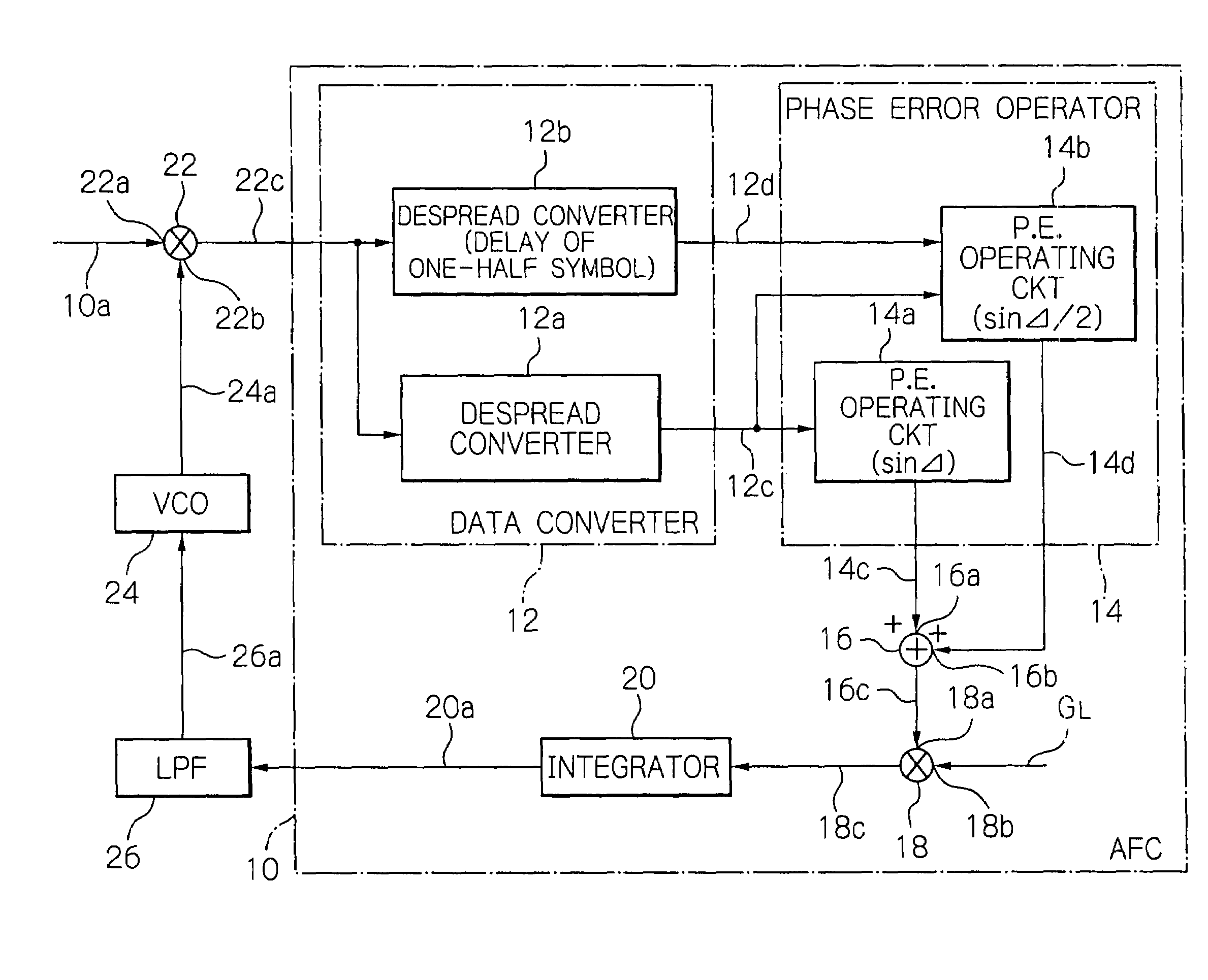
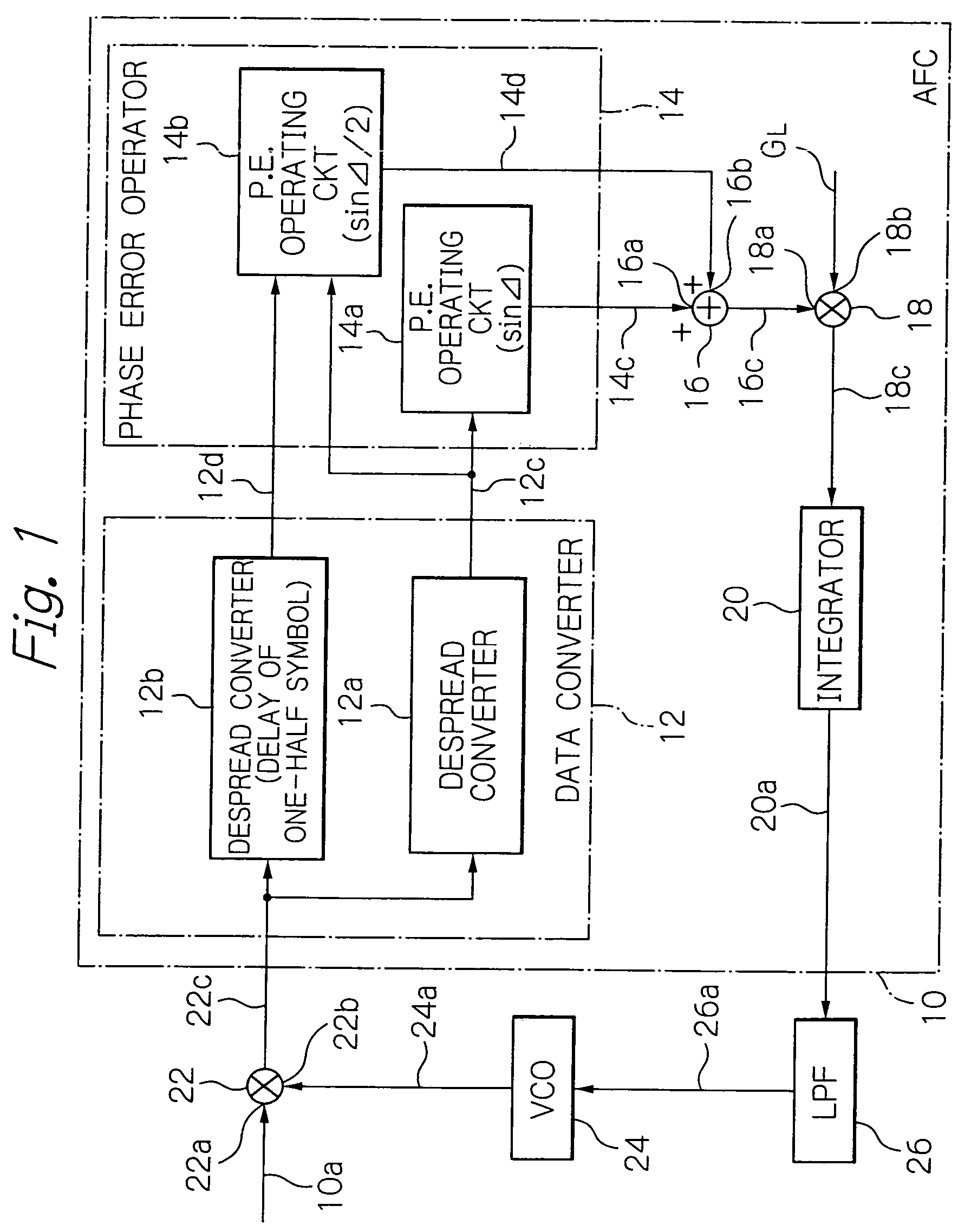
[0019]Referring to the accompanying drawings, preferred embodiments of the present invention will be described in detail. In the present embodiment, the frequency controlling apparatus of the present invention is applied to an automatic frequency controller (AFC) 10. The portions of the automatic frequency controller not directly relevant to understanding the present invention are not illustrated nor described. In the following description, a signal is designated with a reference numeral on which the signal appears.

[0020]Referring to FIG. 1, the automatic frequency controller 10 includes a data converter 12, a phase error operator 14, an adder 16, a multiplier 18 and an integrator 20 interconnected as shown. Outside the automatic frequency controller 10, there are provided a mixer 22, a voltage controller oscillator (VCO) 24 and a low pass filter (LPF) 26 interconnected as illustrated.

[0021]In the following, it is assumed for simplicity in explanation that there are no factors influ...


PUM


Abstract

An automatic frequency controller restores symbols carried on a received signal by a data converter, and uses an in-phase and a quadrature component obtained by phase measurement from the symbol restored by the data converter to calculate first and second phase errors. The first and second phase errors are summed together by an adder to produce a phase error of a waveform more moderate than the first phase error to decrease and increase error correction in the ranges of smaller and larger phase errors, respectively, to elongate a period of positive amplitude to expand the desired range of polarity of the phase error. A multiplier multiplies the result from the summation with a coefficient to normalize it. An integrator integrates the normalized data to produce a control signal for use in restoring the symbols.

Description

BACKGROUND OF THE INVENTION[0001]1. Field of the Invention[0002]This invention relates to a frequency controlling apparatus and, more particularly, to an automatic frequency controller (AFC) for automatically controlling the frequency in a received signal to a predetermined frequency.[0003]2. Description of the Background Art[0004]In receivers for achieving stable reception of signals, an automatic frequency controller (AFC) is used. The automatic frequency controller will now briefly be described. In the receiver, waves received with an antenna are sent to an input port of a mixer, to the other input port of which a carrier wave is supplied from an oscillator, such as a voltage-controlled oscillator (VCO). The mixer down-converts the frequency of the received wave with carrier wave synchronization to an intermediate frequency or a baseband frequency to output the converted signal to an Automatic frequency controller. The mixer also has a quadrature demodulating function and outputs...

Claims


Application Information

Patent Timeline
Patent Type & Authority Patents(United States)
IPC IPC(8): H04L27/227H03J7/02
CPCH03J7/02
Inventor AKAHORI, HIROJI
Owner LAPIS SEMICON CO LTD
Why Eureka
Try Eureka