Precision mirror displacement assembly

a technology of mirror displacement and assembly, which is applied in the direction of instruments, machine supports, other domestic objects, etc., can solve the problems of cables moving slightly, deteriorating quickly, and insufficient robustness of flexure pivots available for use in precision mirror displacement assemblies

Active Publication Date: 2005-12-06
DRS NETWORK & IMAGING SYST
View PDF13 Cites 43 Cited by
  • Summary
  • Abstract
  • Description
  • Claims
  • Application Information

AI Technical Summary

Benefits of technology

[0010]In accordance with the present invention, a precision mirror displacement assembly includes a mirror having a reflective front surface and a backside with an enhanced back surface defining a maximum thickness for the mirror, where the maximum thickness is sufficient to avoid distortion of the reflective front surface that can result from interaction of the mirror with mirror displacement control components, such as a mechanical stop or an actuator, or from manufacture of mirror displacement control components, such as a position sensor target area and a portion of an actuator, on or in the enhanced back surface. The enhanced back surface defines two axially aligned pivot bores. A flexure pivot is secured to the mirror at each of the pivot bores and also to a pivot mount that projects from a base of a housing of the mirror assembly. The flexure pivots, accordingly, define an axis of rotation of the mirror. The enhanced back surface also defines a pair of actuator field bores. The actuator bores are positioned symmetrically about the axis of rotation, and actuator field pieces are secured to the actuator bores. In addition, the enhanced back surface defines a pair of sensor target areas positioned symmetrically about the axis of rotation. Actuator coil pieces and position sensors are secured to the base of the housing and project toward the enhanced back surface opposite to the actuator field pieces and target areas, respectively.
[0011]In a preferred embodiment, the housing encloses an integrated sensor electronics module that is electronically coupled to, and performs signal processing associated with the operation of, the position sensors. The sensor electronics module is electromagnetic radiation shielded by the housing and is connected to the position sensors by very short length electromagnetic radiation shielded interconnecting cables. The sensor module generates a mirror position feedback signal from mirror position data signals received from the position sensors, and then supplies the feedback signal to an external controller module. Based on the feedback signal, the external control module supplies an actuator control signal to an actuator assembly in the mirror assembly. The actuator control signal controls the extent to which the actuator assembly will drive the mirror so that the mirror rotates about the axis of rotation and a precise mirror orientation is achieved.
[0014]In still a further preferred embodiment, the precision mirror assembly includes an adjustable mounting assembly that provides for rigid coupling of the mirror assembly to a larger optical subassembly, such as an infrared sensor, a laser or any optical system requiring a precision mirror displacement assembly. The adjustable mounting assembly includes an adjustable compression spring assembly. The spring assembly defines a pre-loaded adjustment range within which the rigid coupling is maintained and the position of the subassembly relative to the mirror assembly is adjustable without the need to remove any components of the mounting assembly or to apply substantially high forces to the spring assembly to obtain an adjustment. An adjustable mounting assembly is preferably coupled at three locations on the base of the housing of the mirror assembly to provide that the mirror can be adjusted with relative ease in three degrees of freedom in relation to the optical subassembly.

Problems solved by technology

For example, it is known that some flexure pivots available for use in a precision mirror displacement assembly are not sufficiently robust to function, and quickly will deteriorate, in a severe shock and vibration environment, such as exists on an aircraft or satellites.
In many mirror assembly applications, the interconnecting cables are subjected to severe EM radiation, and also to high levels of shock or vibration that causes the cables to move slightly despite their having been secured.
It has been found that the generation of electrical mirror position data signals by a position sensor is adversely affected when the interconnecting cables that extend between the position sensors and an external control module are moved or subjected to severe EM radiation.
Consequently, erroneous mirror position data signals, which do not accurately represent the orientation of the mirror in relation to a neutral plane, are transmitted to the external control module, such that a desired, precise mirror orientation cannot be readily achieved or continuously maintained.
Further, the inclusion of a moving platform in a precision mirror displacement assembly substantially increases the overall size and adds complexity to the manufacture of the mirror assembly.
Distortion of the reflective surface of the mirror, which can adversely affect mirror performance, would likely occur, for example, when forces are applied to the mirror to directly attach an actuator or sensor component to the mirror during manufacture of the mirror assembly, or when a mechanical stop, which limits the angular range of rotation of the mirror, strikes the mirror to halt rotational motion of the mirror.

Method used


Image

  • Precision mirror displacement assembly
  • Precision mirror displacement assembly
  • Precision mirror displacement assembly

Examples


Embodiment Construction

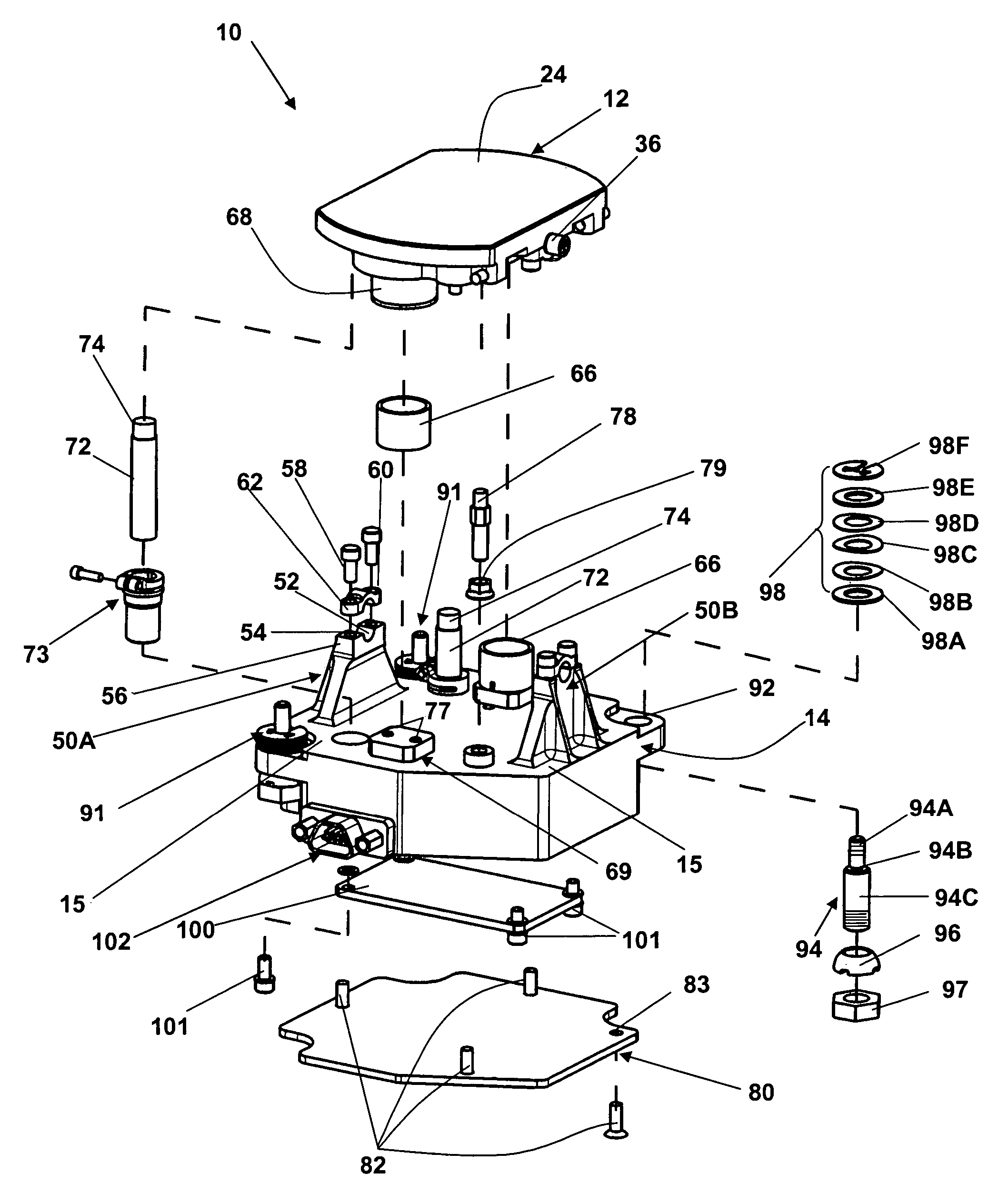
[0023]The present invention of a precision mirror displacement assembly incorporates conventional mirror displacement control components, such as actuators, position sensors, position sensor electronics, flex pivot bearings, mechanical stops, etc., into a compact, integrated, easy to assemble and inexpensive to manufacture assembly, where the assembly includes a mirror having an enhanced backside for direct connection and interaction with mirror displacement control components, where the mirror can be rotated with high precision about an axis of rotation to obtain a precise orientation and where the components of the mirror assembly operate satisfactorily in severe shock, vibration and temperature environments.

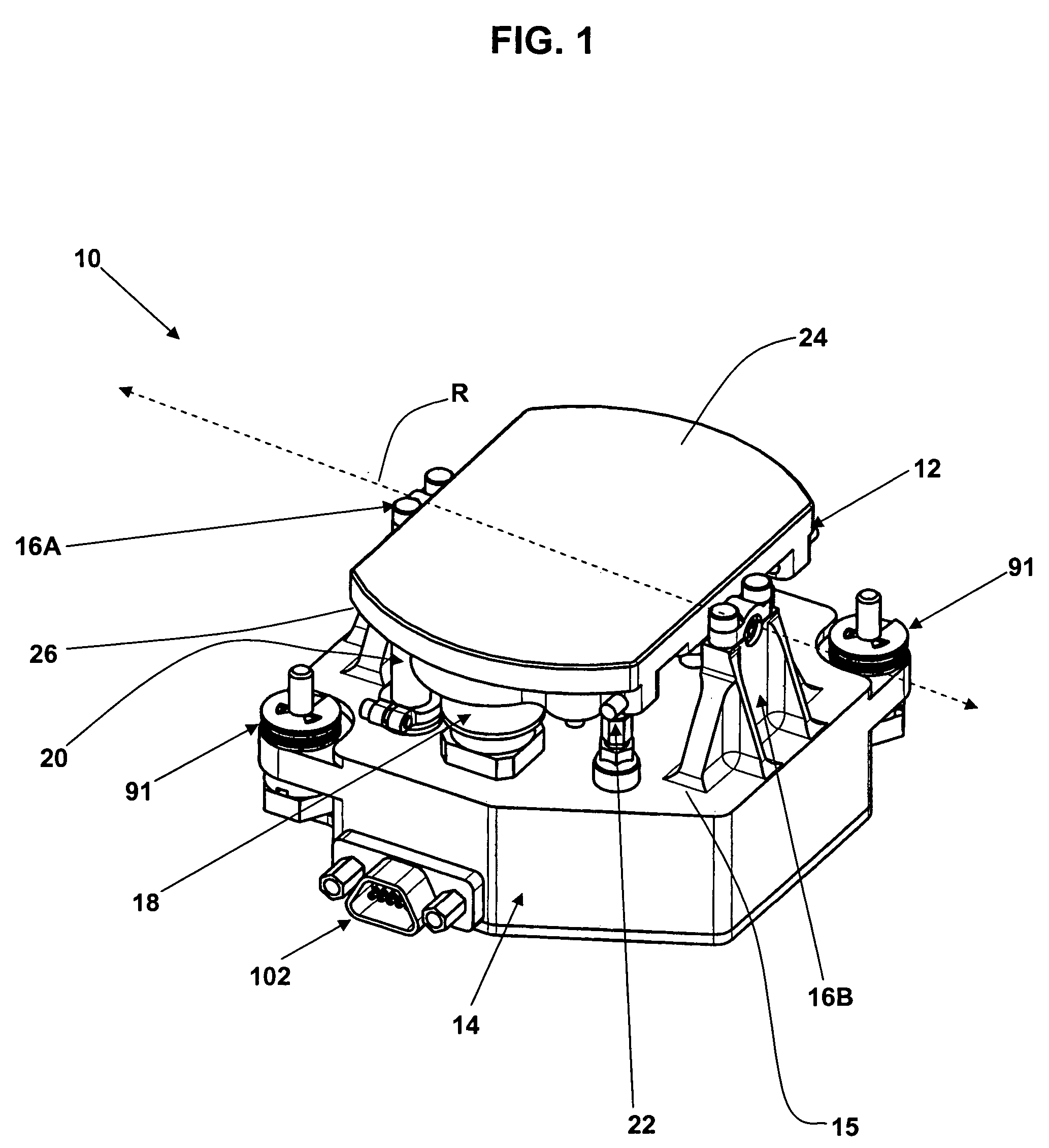
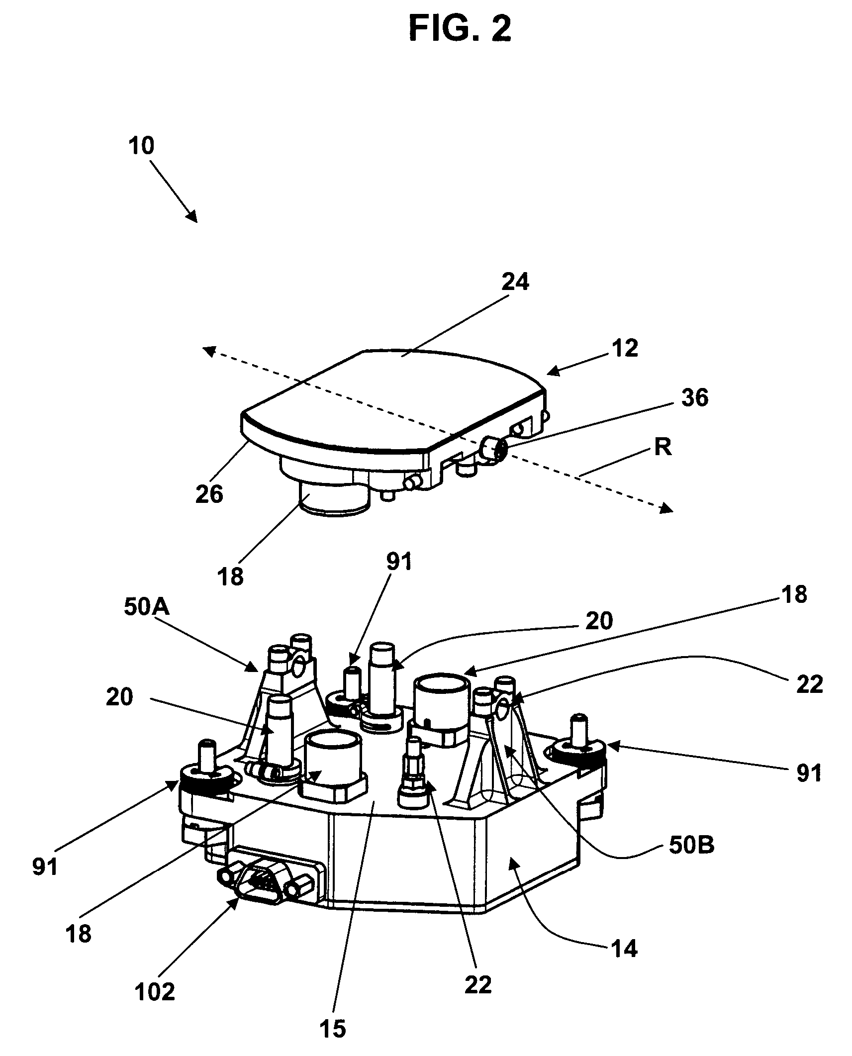
[0024]FIG. 1 illustrates a preferred embodiment of a precision mirror displacement assembly 10 in accordance with the present invention. Referring to FIG. 1, the mirror assembly 10 includes a mirror 12 coupled to a base 15 of a housing 14 by pivot mount assemblies 16A, 16B. Re...


PUM


Abstract

A precision mirror displacement assembly for controlling rotation of a mirror about a rotational axis to obtain a precise mirror orientation includes a mirror having an enhanced backside and a reflective front surface. The enhanced backside has a sufficient thickness to provide that attachment of mirror displacement control components, such as portions of actuator and position sensor assemblies, to the backside during manufacture of the mirror assembly does not cause distortion of the reflective front surface of the mirror. The enhanced backside also is of sufficient thickness to avoid distortion of the front surface based on interaction of the mirror with mechanical stops and actuator components that are attached to a base of a separate housing of the mirror assembly that opposes the backside of the mirror.

Description

CROSS REFERENCE TO RELATED APPLICATION[0001]This application claims the benefit of U.S. Provisional Application No. 60 / 482,144 filed Jun. 24, 2003, assigned to the assignee of this application and incorporated by reference herein.FIELD OF THE INVENTION[0002]The present invention relates generally to directing electromagnetic signals to a precise destination by reflecting the signals, and more particularly, to a precision mirror displacement assembly including a mirror directly coupled to and interacting with mirror displacement control components that precisely control the positioning of the mirror to cause a desired reflection of electromagnetic signals directed to the mirror.BACKGROUND OF THE INVENTION[0003]Current precision mirror displacement assemblies include various types of mirror displacement control components that provide for high precision rotation of a mirror through a range of angular orientations. See, for example, U.S. Pat. Nos. 5,110,195 and 6,535,319, incorporated ...

Claims


Application Information

Patent Timeline
Patent Type & Authority Patents(United States)
IPC IPC(8): G02B7/182
CPCG02B7/182
Inventor HILEY, DAVEFLATHOM, JASONKIANI, TALPALOMBO, MARIOBERNAL, JOSE A.
Owner DRS NETWORK & IMAGING SYST
Why Eureka
Try Eureka