
Apparatus and method to implement a flexible hub-spoke satellite communications network

a satellite communications network and flexible technology, applied in the field of communication, can solve the problems of inability to reconfigure satellites in orbit, inability to build excess capacity in satellites, and high implementation costs, and achieve the effect of maximum feasible bandwidth, low cost, and simple implementation of on-orbit flexibility

Inactive Publication Date: 2005-12-06
NORTHROP GRUMMAN SYST CORP
View PDF10 Cites 23 Cited by
  • Summary
  • Abstract
  • Description
  • Claims
  • Application Information

AI Technical Summary

Benefits of technology

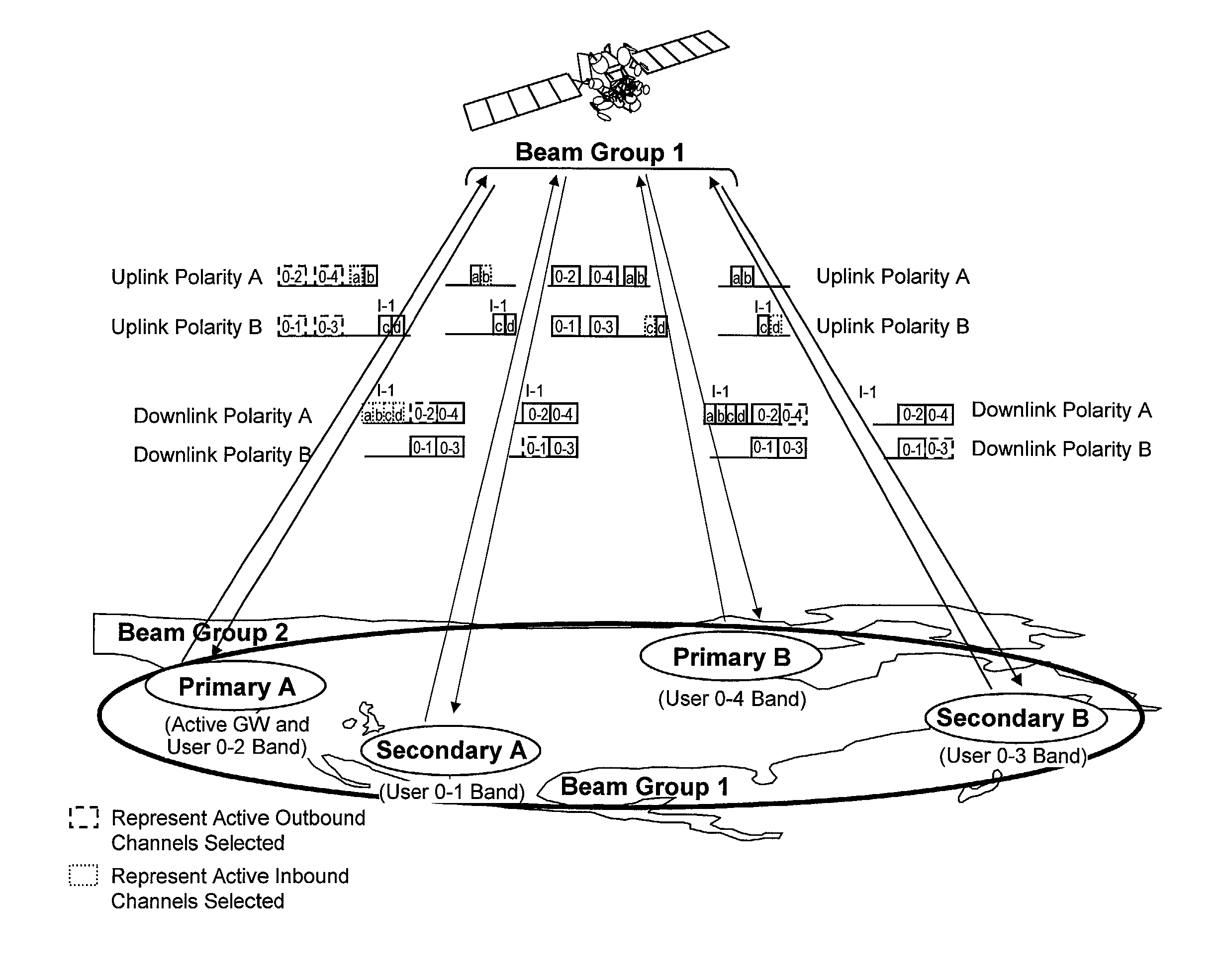
[0010]The preferred embodiments involve a satellite communications network having the maximum feasible bandwidth and on-orbit capacity reallocation capability. This general objective is provided by a practical and simple implementation of the on-orbit flexibility enabled by modern antenna designs which is low cost, low mass and low power.
[0011]An objective of the preferred embodiments is to provide a hub-spoke communications network based on a multi-beam satellite that can on-orbit, for an uplink beam, pull off signal information, in real-time from each spot beam within a chosen group and input the signal information into a flexible uplink implementation. The flexible uplink implementation selects a combination of spot beams and processes the desired uplink capacity for each beam. Such a network provides maximum bandwidth and on-orbit reallocation of channel capability between spot beams in any chosen beam group.
[0012]The preferred embodiments also seek to eliminate the cost and mass of an on-orbit test unit, or the expense of multiple test sites. The preferred embodiments provide the ability to test from a single site via connectivity switching.
[0014]In a second aspect of the invention, the switches and multiplexer provide an inexpensive, on-orbit method to enable a spot beam by spot beam checkout and test. The flexible uplink allows connectivity, for test purposes only, of the uplink from each cell to the downlink to the same cell. In other words, it allows each cell to act as a gateway in terms of uplink signal connectivity. This allows testing of all spot beams from a single test site—the site generates an uplink and observes the downlink. Performance within each beam is tested by re-pointing the satellite antennas in a scan pattern. Each beam can be tested this way in turn by repositioning the beams and commanding the appropriate uplink connectivity. This configuration allows the test signal from one earth station to be used to test each satellite spot beam one by one. This allows each user beam to look like the gateway for the purposes of test.

Problems solved by technology

However, this redundancy is expensive to implement since two satellites must be used just in case one fails.
Further, should demand increase in one location, it may not be possible to reconfigure the satellites in orbit to handle the additional load from the increased traffic seen in one area.
In addition, building excess capacity in a satellite may not be possible at the time the satellite is being designed since that may be more than one year in advance of launch.
There may be uncertainty in market demand at that time.
However, unlike a uniform coverage distribution methodology, the spot beams may be directed towards those areas where demand is highest and profitability maximized.
The problem with this approach is that demand for the system is highly uncertain, and it is likely that some cells will have over-allocated resources while others will have under-allocated resources.
The result is a lower ability to sell capacity and sharply lower system revenues.
Systems with hard-wired connectivity are difficult to test.
However, when a satellite is capable of receiving and transmitting a large number of beams then logistical problems may occur during the testing phase.
In such a circumstance, it may be expensive and extremely difficult and laborious to test each uplink beam and each downlink beam.
This type of testing is extremely laborious as it may involve a large number of ground stations for transmitting or receiving the beams.
On-board test signal generators are also known, but this solution is also expensive.

Method used


Image

  • Apparatus and method to implement a flexible hub-spoke satellite communications network
  • Apparatus and method to implement a flexible hub-spoke satellite communications network
  • Apparatus and method to implement a flexible hub-spoke satellite communications network

Examples


Embodiment Construction

[0024]The preferred embodiments of the present invention will now be described with respect to a multi-beam satellite that includes an input section set to receive a plurality of beams in a beam group (from Earth) and an output section set to transmit a plurality of beams in a beam group (to Earth). A payload architecture is coupled between the input section and the output section. The payload architecture includes a flexible implementation to provide a combination of switching and filtering signals corresponding to the first plurality of beams (i.e., uplink beams) received at the input section and routed to the output section to be transmitted as the second plurality of beams (i.e., downlink beams)to give specific desired operational benefits. The preferred embodiments are merely exemplary, and are in no way intended to limit the invention or its applications or uses. The terminologies of signal, signals, beam or beams may be used throughout and are meant to be interchangeable.

[002...


PUM


Abstract

A multi-beam satellite comprises an input section receiving a plurality of first spot beams and an output section transmitting a plurality of second spot beams. A payload architecture is coupled between the input section and output section. It flexibly and selectively switches and filters the first plurality of spot beams received by the input section and provides signals to the output section to be transmitted as the second plurality of spot beams.

Description

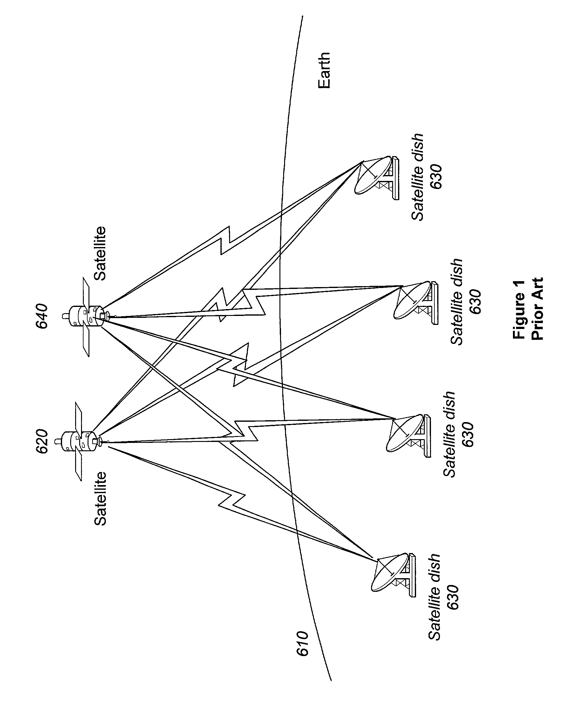
BACKGROUND OF THE INVENTION[0001]1. Field of Invention[0002]This invention relates generally to the field of communications. In particular, the invention relates to apparatus and methods to implement a flexible hub-spoke satellite communications network.[0003]2. Discussion of the Related Art[0004]Conventionally, communication satellites were confined to telephone communications. However, all forms of communication are now being relayed by geo-synchronous satellites including, but not limited to, voice, data, video, television, and radio. Several major industries are heavily dependent upon reliable satellite communications service being continuously available. FIG. 1 is an illustration of a conventional satellite communications network in which two satellites provide redundancy for communications. Satellites 620 and 640 communicate with ground stations 630 located within a region of Earth 610 using a uniform coverage distribution methodology. This uniform coverage distribution method...

Claims


Application Information

Patent Timeline
IPC IPC(8): H04B7/19H04B7/185H04B7/204
CPCH04B7/18519H04B7/2041
Inventor FRANZEN, DANIEL R.LANE, DANIEL R.DICAMILLO, NICHOLAS F.
Owner NORTHROP GRUMMAN SYST CORP
Learn More