
Method and system for designing an impingement film floatwall panel system

Inactive Publication Date: 2005-12-06
RAYTHEON TECH CORP
View PDF5 Cites 60 Cited by
  • Summary
  • Abstract
  • Description
  • Claims
  • Application Information

AI Technical Summary

Problems solved by technology

While the ICAD system provides an excellent tool for developing software product models, it is not a replacement for an organization's primary CAD system, which maintains the product model definition throughout the entire product design and manufacturing cycle.
For example, while the ICAD system can create a geometric model, it cannot easily create drawings based on that model or support other aspects of the design process typically provided by CAD systems.
Another inherent problem with the commercial ICAD system is that the parametric model created by the product model software program cannot be transported as a similar parametric product model into a Unigraphics CAD system.
Furthermore, since it is difficult to make modifications to a non-parametric model in Unigraphics, revisions to the product model must normally be made in the ICAD system and re-imported into Unigraphics.
This causes any additional features previously added in Unigraphics to be lost.
On the other hand, the Unigraphics CAD system has inherent problems in that not all of the parametric models created by Unigraphics are “standardized” within an organization or industry.
Also, parametric models implemented in Unigraphics do not effectively implement a KBE system (similar to the ICAD system) that requires the model configuration and order of Boolean operations to vary according to design requirements.
Also, a Unigraphics parametric model cannot be structured to provide parameter relationships that satisfy both design and manufacturing requirements.

Method used


Image

  • Method and system for designing an impingement film floatwall panel system
  • Method and system for designing an impingement film floatwall panel system
  • Method and system for designing an impingement film floatwall panel system

Examples


Embodiment Construction

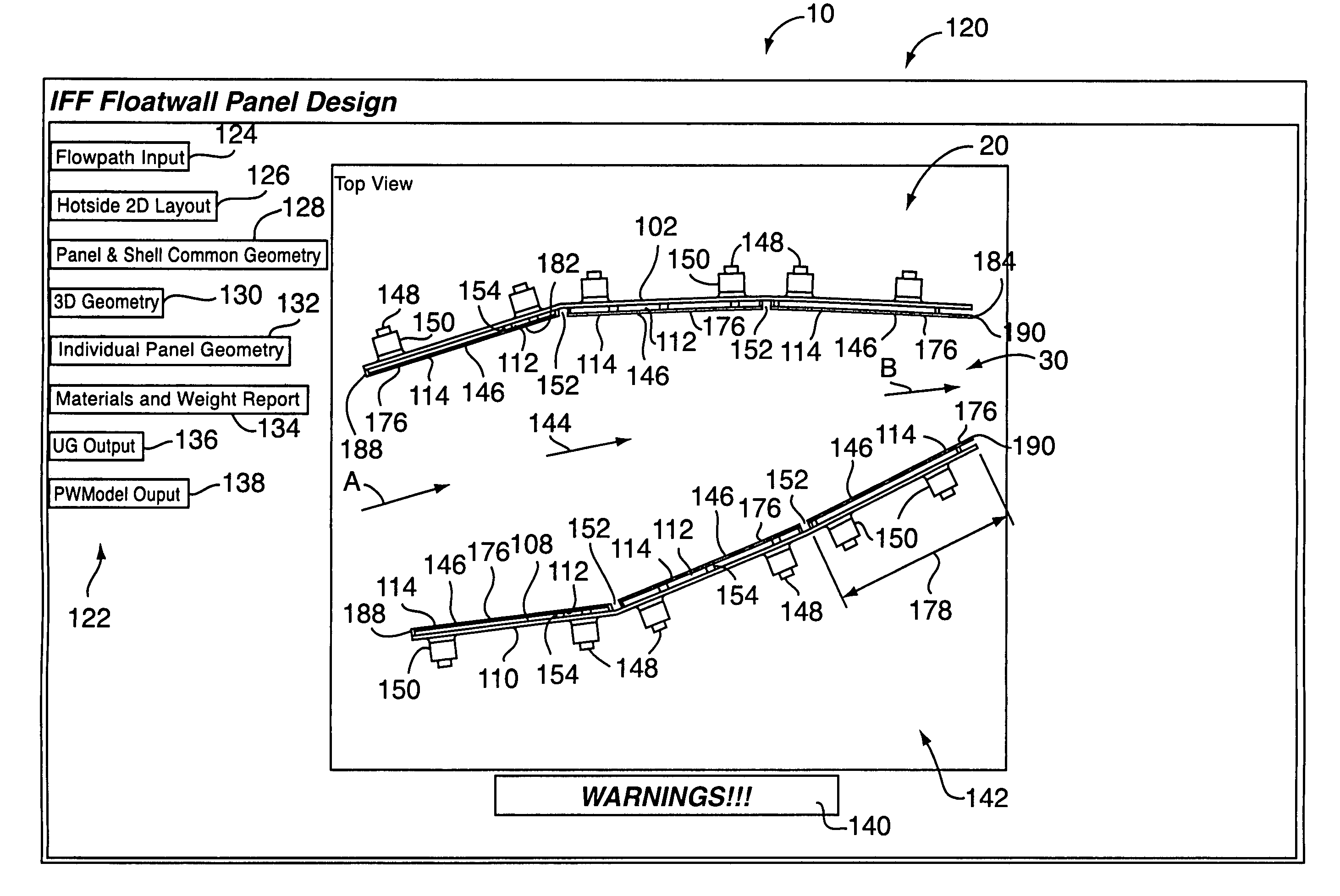
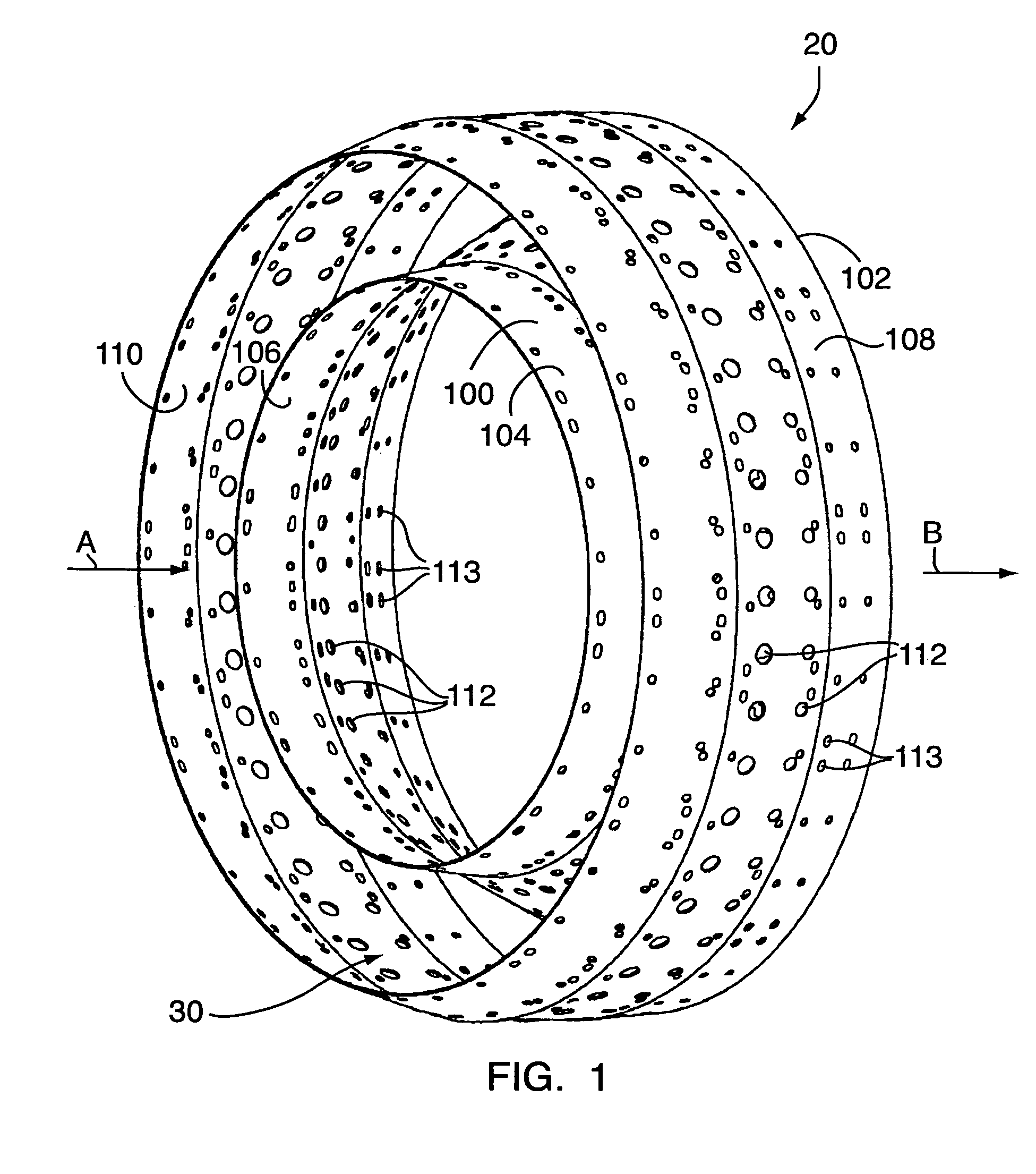
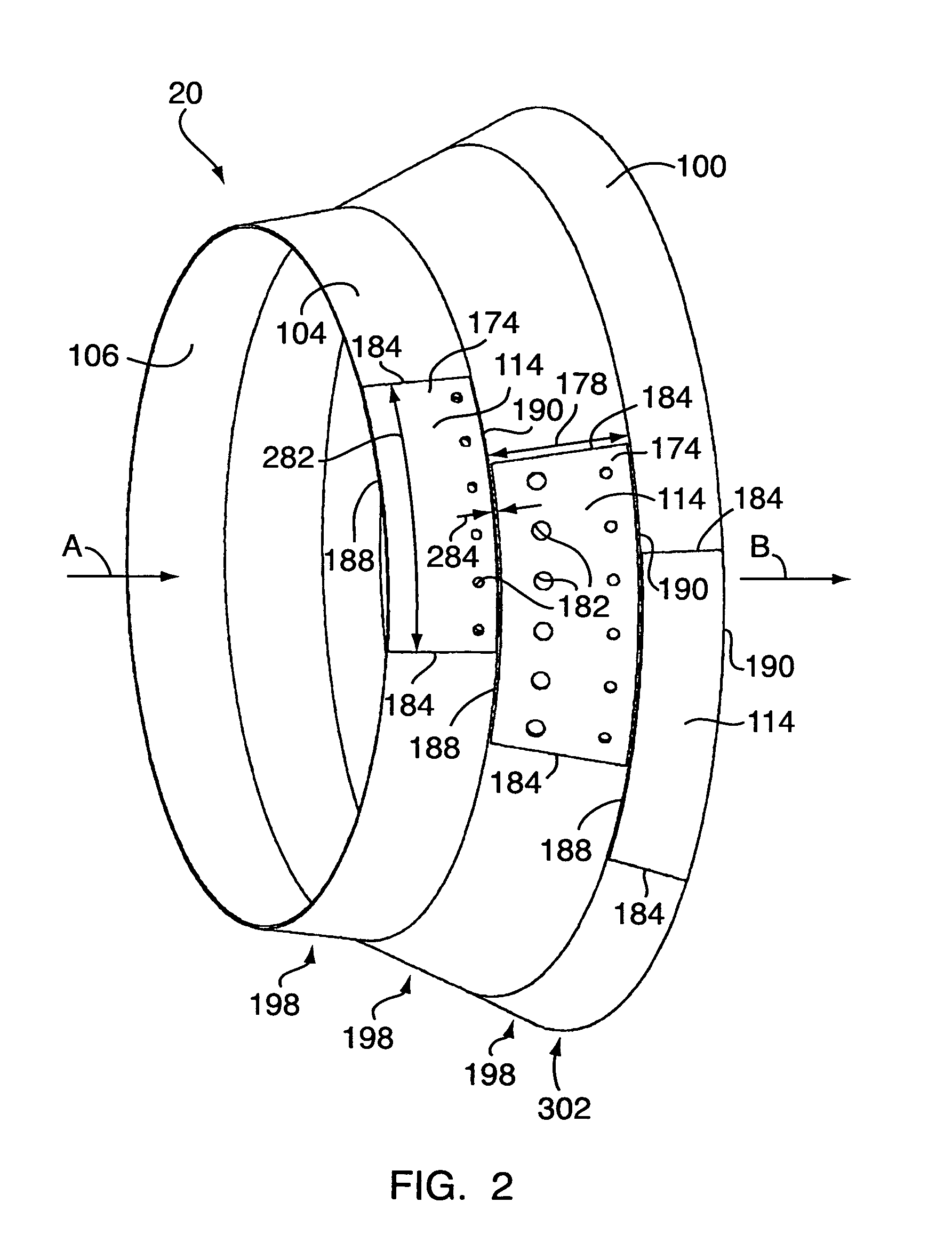
[0028]Referring to the figures in general, in an exemplary embodiment of the present invention, the invention generally comprises an algorithm embodied in a knowledge-based, product model software program 10 that creates a model 20 of impingement film floatwall panel system including impingement film floatwall panels and supporting shells for a combustion chamber 30 of a gas turbine engine. The resulting impingement film floatwall panels and supporting shells may then be manufactured from the model 20. The product model software program 10 may preferably be embodied in the aforementioned ICAD system, commercially available from Knowledge Technologies, Inc., and operating within a workstation, such as that available from Sun Microsystems or Silicon Graphics. The method and the apparatus of the present invention enables the rapid creation and manipulation of a parametric, three-dimensional, geometric model 20, or geometric representation 20, of the floatwall panels and supporting shel...


PUM


Abstract

A method and system for designing an impingement film floatwall panel system for a combustion chamber for a gas turbine engine comprising the steps of creating an impingement film floatwall panel knowledge base of information. The knowledge base has a plurality of design rule signals with respect to a corresponding plurality of parameter signals of associated elements of impingement film floatwall panels for a combustion chamber, wherein the knowledge base comprises at least one data value signal for each one of the plurality of design rule signals. The steps also include entering a desired data value signal for a selected one of the plurality of parameter signals of an associated element of the impingement film floatwall panels and comparing the entered desired data value signal for the selected one of the plurality of parameters with the corresponding at least one data value signal in the knowledge base for the corresponding one of the plurality of design rule signals. If the result of the step of comparing is such that the entered desired data value signal for the selected one of the plurality of parameter signals is determined to have a first predetermined relationship with respect to the corresponding at least one data value signal in the knowledge base for the selected one of the plurality of design rule signals, create signals representative of a geometric representation of the selected one of the plurality of parameter signals of the associated element of the impingement film floatwall panels.

Description

BACKGROUND OF THE INVENTION[0001]Some of the subject matter disclosed herein is related to the subject matter of commonly owned U.S. patents and patent applications: U.S. patent application Ser. No. 09 / 212,922, filed on Dec. 16, 1998, entitled “Method of Designing a Turbine Blade Outer Air Seal” and issued on May 21, 2002 as U.S. Pat. No. 6,393,331; U.S. patent application Ser. No. 09 / 520,085, filed on Mar. 7, 2000, entitled “Method and System for Designing a Spline Coupling” and issued on Jul. 1, 2003 as U.S. Pat. No. 6,587,741; U.S. patent application Ser. No. 09 / 511,549 filed on Feb. 23, 2000, entitled “Method and System for Designing a Low Pressure Turbine Shaft” and issued Sep. 23, 2003 as U.S. Pat. No. 6,625,507; and U.S. patent application Ser. No. 09 / 608,620 filed on June 30, 2000 entitled “Method and System for Designing Frames and Cases”. All of the foregoing patent applications are hereby incorporated by reference.FIELD OF THE INVENTION[0002]This invention relates general...

Claims


Application Information

Patent Timeline
IPC IPC(8): F23R3/00G06G7/48
CPCF23R3/002F23R2900/00018Y10T477/40Y02T50/675F23R2900/03044Y02T50/60
Inventor FORTIN, THOMAS B.CHETTA, GREGORY E.LEUNG, DAVID W.MEYERS, DUNCAN C.BELSON, KEITH C.DIAZ, JOHN V.HOLLADAY, THOMAS E.LADD, SCOTT A.MCKINNEY, RANDALL G.RINELLA, SERGIOSADIL, ANDREASTITTERTON, III, GEORGE F.
Owner RAYTHEON TECH CORP
Learn More