Gas turbine combustor, gas turbine, and jet engine

a technology of gas turbines and combustor blades, which is applied in the direction of machines/engines, burner noise reduction, lighting and heating apparatus, etc., can solve the problems of large pressure fluctuations of combustor blades, difficult normal operation of gas turbines and jet engines, and possible combustion oscillations, so as to prevent resonance in the members and reduce the effect of combustion oscillations

Inactive Publication Date: 2005-12-13
MITSUBISHI HITACHIPOWER SYST LTD
View PDF13 Cites 34 Cited by
  • Summary
  • Abstract
  • Description
  • Claims
  • Application Information

AI Technical Summary

Benefits of technology

[0030]Therefore, in the jet engine of present invention, by applying the above combustor, the combustion oscillations can be reduced. As a result, it is possible to prevent resonances in members which can form an acoustic system, such as a combustor or a gas turbine.

Problems solved by technology

However, the above conventional gas turbine combustor, gas turbine, and jet engine have the following problems.
While the combustion of premixed air having a uniform concentration has the advantage of reduced NOx emissions, in contrast, a problem is that the combustion oscillations may occur because of the increase of generated heat per unit volume because the combustion occurs in a restricted area in a short period of time.
Such combustion oscillations propagate as pressure waves, and may resonate with parts which can form acoustic systems such as a casing of a combustor or a gas turbine, and because there is the concern that the internal pressure fluctuations of the combustor may become large, normal operation of the gas turbine and the jet engine is difficult under such conditions.
Also, the turbulence of the air flow provided by the compressor is strong and not readily attenuated, therefore, the combustion tends to be unstable.
This instability in the combustion may also give rise to pressure waves in the internal pressure fluctuations in the combustor, these pressure waves may propagate, and may resonate with parts which can form an acoustic system such as a casing of a combustor or a gas turbine in some conditions.
Accordingly, there is the concern that the internal pressure fluctuations of the combustor may become large, and normal operation of the gas turbine and the jet engine is difficult under such conditions.
In this type of gas turbine combustor, however, the porous wall-cylinder is disposed so as not to intervene plate-fins which are the combustion region, therefore decreasing effect of combustion oscillation has not been achieved sufficiently.

Method used


Image

  • Gas turbine combustor, gas turbine, and jet engine
  • Gas turbine combustor, gas turbine, and jet engine
  • Gas turbine combustor, gas turbine, and jet engine

Examples


Embodiment Construction

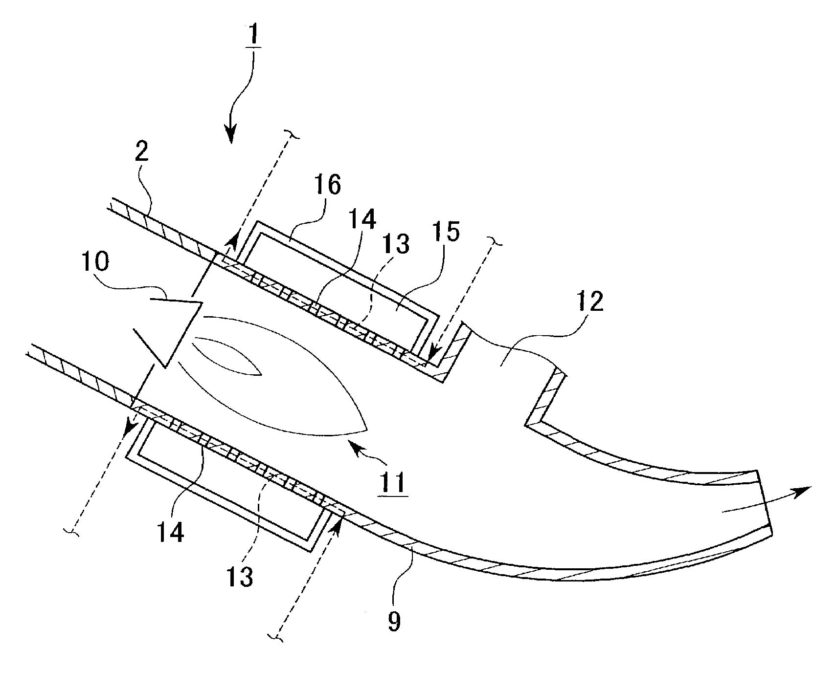
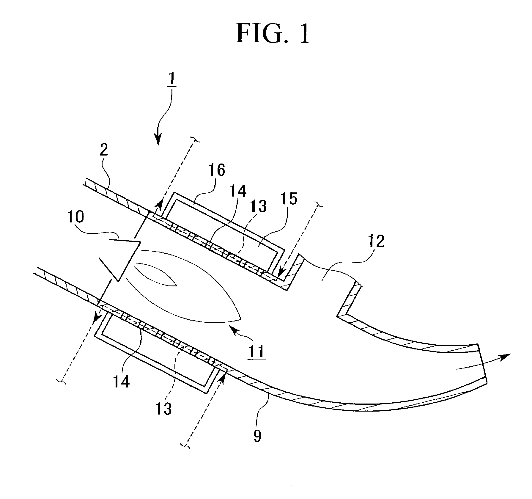
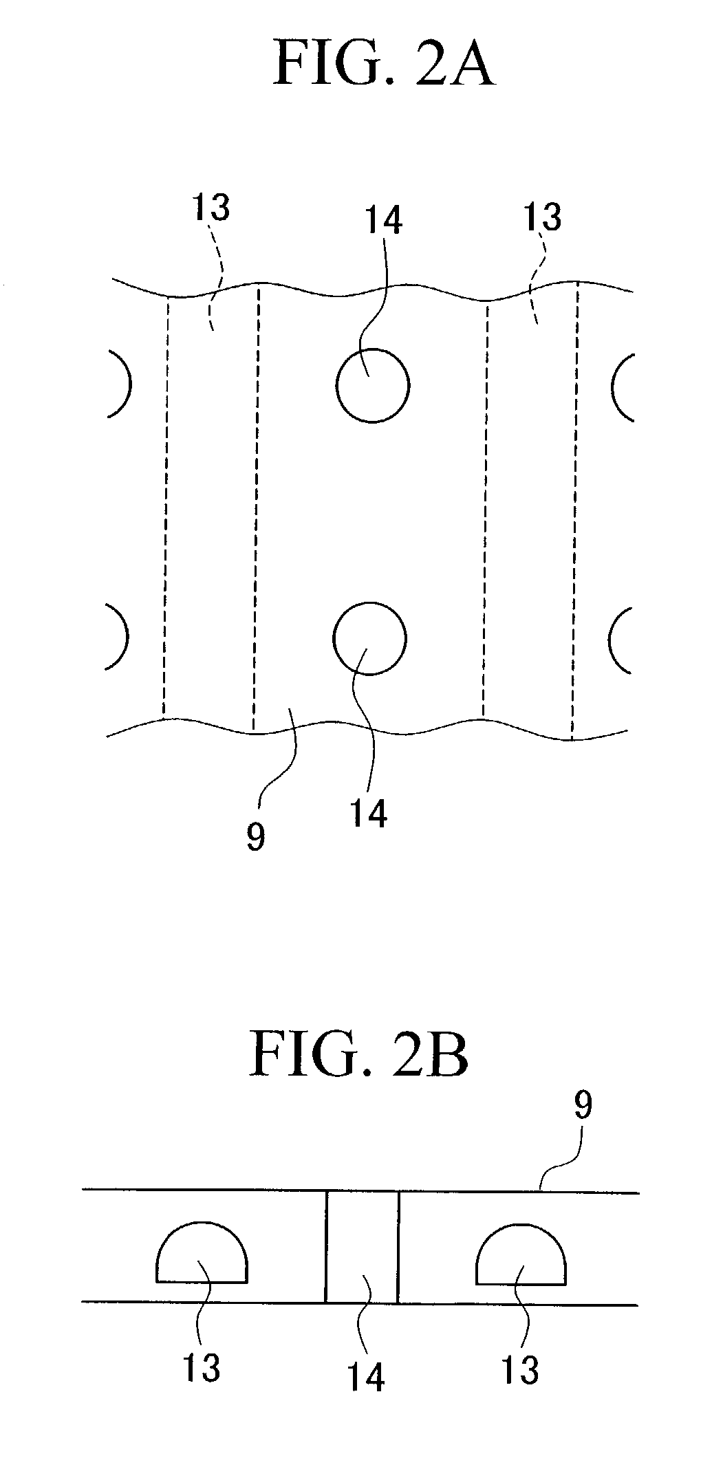
[0043]The first embodiment of gas turbine combustor, gas turbine, and jet engine in present invention is explained as follows.

[0044]This type of gas turbine and the jet engine mainly comprise a compressor, a combustor, and the turbine as described for the prior art. The gas turbine rotates the main spindle by expanding the high temperature high pressure gas in the turbine, and generates the shaft output which is used as a driving force for a equipment such as an electric generator. The jet engine rotates the main spindle by expanding the high temperature high pressure gas in the turbine, and exhausts a high speed jet (discharge air) to provide kinetic energy which is used as a driving force of an aircraft from the exit of the turbine.

[0045]Among the components of above structure, the compressor introduces and compresses the air as working fluid, and supplies the air flow to the combustor. In this compressor, an axial flow compressor which is combined with the turbine via the main sp...


PUM


Abstract

For the purpose of reduced NOx gas emission, a gas turbine engine comprises a cylinder having a combustion region inside of the cylinder; a resonator having a cavity and provided around the surface of the cylinder and sound absorption holes formed on the cylinder and having opening ends on the cylinder.

Description

BACKGROUND OF THE INVENTION[0001]1. Field of the Invention[0002]The present invention relates to a gas turbine combustor which can reduce the oscillations due to combustion, a gas turbine, and a jet engine which is provided with this combustor.[0003]2. Description of Related Art[0004]For gas turbines which output shaft power by compressing air as a working fluid and heating it in a combustor, and expanding the thus produced high temperature and high pressure gas in a turbine, and for also jet engines used to directly propel aircraft by the kinetic energy produced by the output of a high speed jet in recent years, there has been demand for a reduction in emissions such as nitrogen oxides (NOx) from the environmental viewpoint.[0005]These gas turbines and jet engines have a compressor, a combustor, and a turbine as their principle components, and the compressor and the turbine are directly connected to each other by a main shaft. The combustor is connected to the outlet port of the co...

Claims


Application Information

Patent Timeline
Patent Type & Authority Patents(United States)
IPC IPC(8): F23M20/00
CPCF23M20/005F23D2210/00F23R2900/00014
Inventor SUENAGA, KIYOSHIMANDAI, SHIGEMIONO, MASAKITANAKA, KATSUNORI
Owner MITSUBISHI HITACHIPOWER SYST LTD
Why Eureka
Try Eureka