Chain stitch sewing mechanism

a chain stitch and sewing mechanism technology, applied in the field of chain stitch sewing mechanism, to achieve the effect of convenient construction

Active Publication Date: 2005-12-13
PFAFF INDUSTRIESYSTEME & MASCH GMBH
View PDF7 Cites 6 Cited by
  • Summary
  • Abstract
  • Description
  • Claims
  • Application Information

AI Technical Summary

Benefits of technology

[0004]The invention has as its object the provision of a sewing mechanism of the previously mentioned kind, which is not only functionally reliable but is also easy to construct.
[0006]In the case of the sewing mechanism according to the invention, the thread catcher moves only up and down and moreover retains a position at which the hook opening faces oppositely to the sewing direction. Accordingly, the danger of the thread catcher catching the already laid down thread loop on the upper surface of the sewn material upon the drawing up of the new thread loop is avoided. On the other hand, by way of the thread puller, the new thread loop hanging in the thread catcher and the upper position of the thread catcher is tensioned, so that it can not slide from the thread catcher when the thread catcher reverses its movement direction in order to again insert itself into the sewn material. In this way, it is assured that the thread catcher during its downward movement will be inserted through the loop and into the sewn material and that the new loop upon the return movement of the thread catcher will be pulled through the loop laid onto the upper side of the sewn material. The mechanism of the invention is simply to realize and assures a true chain formation.
[0009]Since the sewing head in total has a relatively large mass, it is advantageous if it can be moved continuously to avoid a constant braking and acceleration of the sewing head. To make such a continuous movement possible, at least the needle and the thread catcher, and as the case may be perhaps also the thread puller, are advantageously arranged, together with their individual drives, on a frame in the sewing head housing which frame is movable back and forth parallel to the sewing direction, so that the sewing head as a whole can be moved in the sewing direction when the needle and / or the thread catcher are still located in the sewn material. As soon as the thread catcher and the needle have both been withdrawn from the sewn material, the frame follows up the sewing head movement inside of the sewing head housing, until the needle again moves into the sewn material.

Problems solved by technology

In order to move the thread catcher both linearly up and down and also to rotate it back and forth about its linear movement path, a complicated mechanism necessary.

Method used


Image

  • Chain stitch sewing mechanism
  • Chain stitch sewing mechanism
  • Chain stitch sewing mechanism

Examples


Embodiment Construction

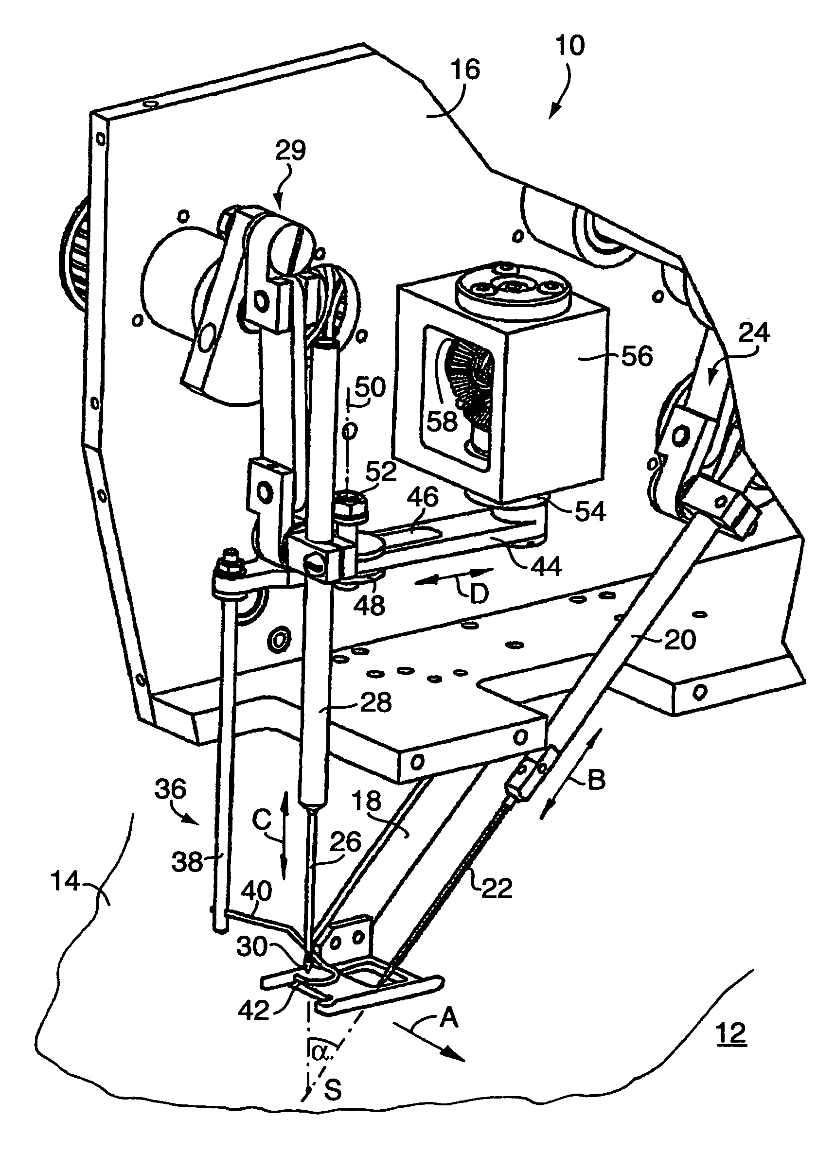
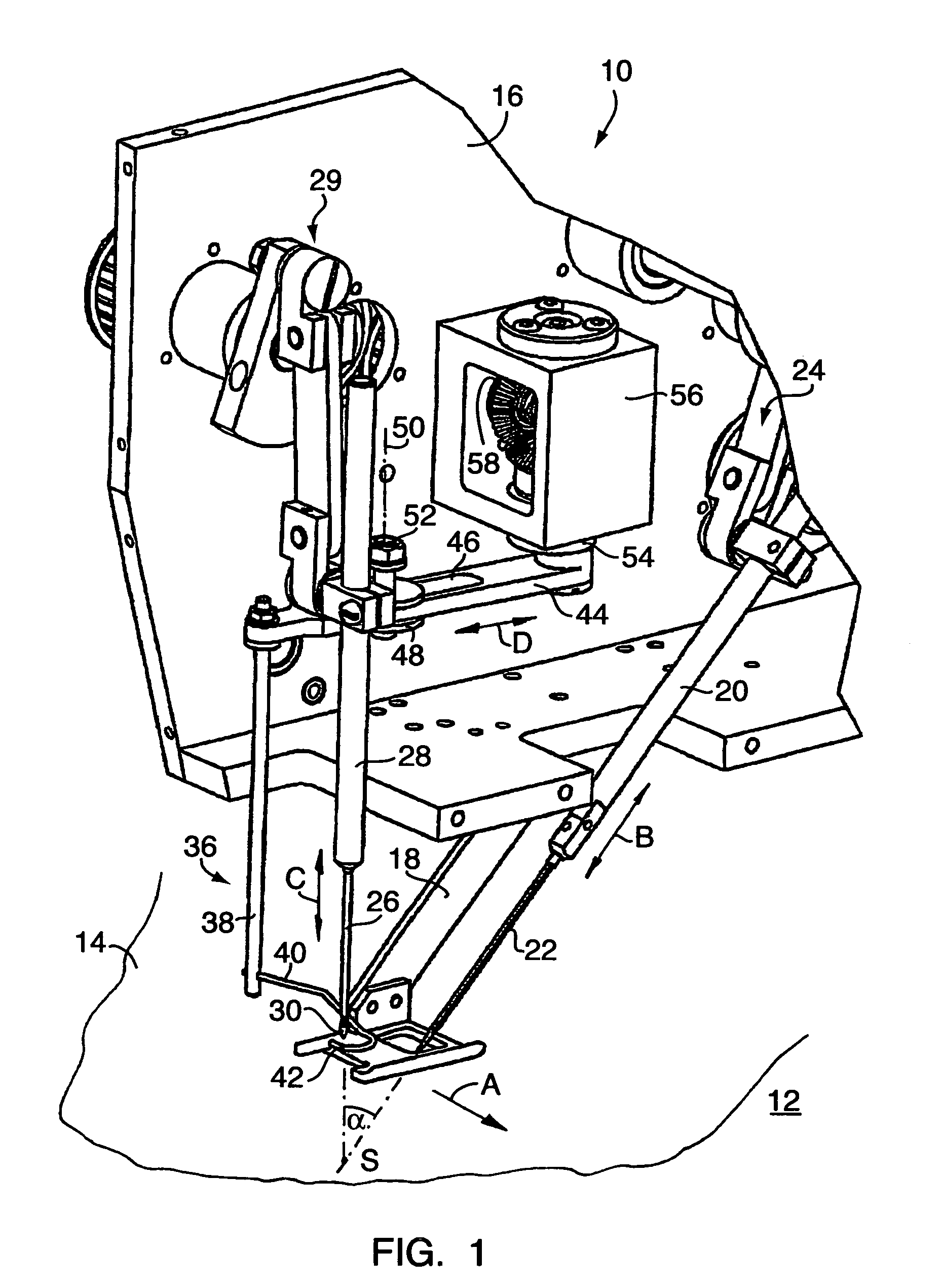
[0015]In FIG. 1 a sewing head is schematically illustrated at 10, which sewing head in a way known in itself can hang from a non-illustrated robot arm and with the help of the robot can be moved in the direction of the arrow A parallel to a sewn material support surface 12 over a sewn material 14 lying on the support surface. A sewn material hold-down 18 is arranged on the housing 16 of the sewing head 10. Further shown is a needle rod 20 which carries a needle 22 and which is movable back and forth in the direction in the arrow B by an incompletely illustrated drive 24. The needle 22 is designed to stick through the sewn material 14 and with this action to pull a thread through the sewn material 14.

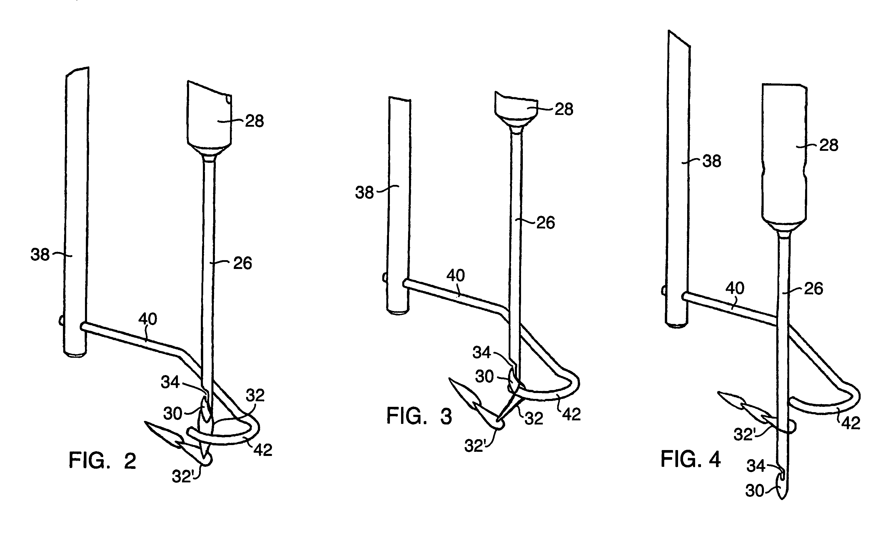
[0016]Further, a needle shaped thread catcher 26 is arranged on the sewing head, which thread catcher is held by a catcher rod 28 and is movable up and down in the direction of the arrow C essentially perpendicularly to the sewn material support surface 12 by a catcher drive 29 inside of...


PUM


Abstract

In a chain stitch sewing mechanism with a sewing head movable parallel to the sewn material plane, including a needle rod with a needle drive for reciprocating a thread carrying needle, a catcher drive for reciprocating a needle shaped thread catcher with an open catching hook. The needle and thread catcher have movement paths forming a sharp angle with one another whose apex lies beneath the sewn material plane and the needle and catcher being so controlled such that a loop formed by the withdrawal of the needle is caught by the thread catcher and pulled through the material. A thread puller on a movable thread arm is moved towards the thread catcher and cooperates with the thread catcher for deflecting the loop hanging off the thread catcher at an angle to the movement path of the thread catcher toward the side opposite to that of the hook opening.

Description

CROSS-REFERENCE TO RELATED APPLICATION[0001]This application is entitled to the benefit of and incorporates by reference essential subject matter disclosed in German Patent Application No. 10 2004 012 822.7 filed on Mar. 16, 2004.BACKGROUND OF THE INVENTION[0002]The invention concerns a chain stitch sewing mechanism with a sewing head movable parallel to a sewn material plane, including a needle rod for a thread carrying needle, a needle drive for a moving the needle rod linearly back and forth at an angle to the sewn material plane, a needle shaped thread catcher provided with an open catching hook and a catcher drive for linearly moving the thread catcher back and forth at an angle to the sewn material plane, with the movement paths of the needle and of the thread catcher forming a sharp angle with one another whose apex lies below the sewn material plane, and with the needle drive and the catcher drive being so controlled that upon a withdrawal of the needle from the sewn materia...

Claims


Application Information

Patent Timeline
Patent Type & Authority Patents(United States)
IPC IPC(8): D05B1/06D05B23/00D05B57/02D05B61/00D05B85/00
CPCD05B1/06D05B57/02D05B61/00D05B85/006
Inventor RATTAY, FRANK
Owner PFAFF INDUSTRIESYSTEME & MASCH GMBH
Why Eureka
Try Eureka