Apparatus for increasing the quality of sound from an acoustic source

a technology of acoustic source and enclosure, which is applied in the direction of transducer details, electric apparatus casings/cabinets/drawers, instruments, etc., can solve the problems of reducing and reducing the sound quality of the enclosure. , to achieve the effect of maximizing the total area of the sound passag

Inactive Publication Date: 2005-12-13
CORTECH
View PDF20 Cites 44 Cited by
  • Summary
  • Abstract
  • Description
  • Claims
  • Application Information

AI Technical Summary

Benefits of technology

[0012]It is therefore an object of the present invention to provide an apparatus capable maximizing the total area of a sound passa

Problems solved by technology

Nevertheless, acoustic principles demand relatively lengthy transmission lines or acoustic paths.
Space restrictions in houses, vehicles, and mobile stereos, however, limit the use of such acoustic paths and the relatively large enclosures that house them.
The folded or labyrinth designs for acoustic paths require sharp bends that disrupt airflow, and thus degrade sound quality and increase mechanical noise.
Further, known devices incorporate relatively long acoustic paths that are unsuitable for use in close quarters (e.g., apartments and car stereos).
The single helix design, however, fails to recognize the benefits of a double helix structure.
Although both patents address the problem of sharp or acute bends in the sound passage, the '969 and '676 patents fail to recognize the advantages of incorporating two sound passages in the shape of a double helix.
This design, wherein the radius of the acoustic channel is a fraction of the total radius of the enclosure or inner sleeve, recognizes the need to maximize space, yet sacrifi

Method used


Image

  • Apparatus for increasing the quality of sound from an acoustic source
  • Apparatus for increasing the quality of sound from an acoustic source
  • Apparatus for increasing the quality of sound from an acoustic source

Examples


Embodiment Construction

[0023]The present invention will now be described more fully hereinafter with reference to the accompanying drawings, in which a preferred embodiment of the invention is shown. This invention may, however, be embodied in many different forms and should not be construed as limited to the embodiments set forth herein. Rather, these embodiments are provided so that this disclosure will be thorough and complete, and will fully convey the scope of the invention to those skilled in the art. Like numbers refer to like elements throughout.

[0024]The term “wave”, and in particular “acoustic wave”, will refer to a disturbance traveling through a medium, for example, a sound wave traveling through an air mass. Hence, the terms wave, acoustic wave, and sound wave may be used interchangeably.

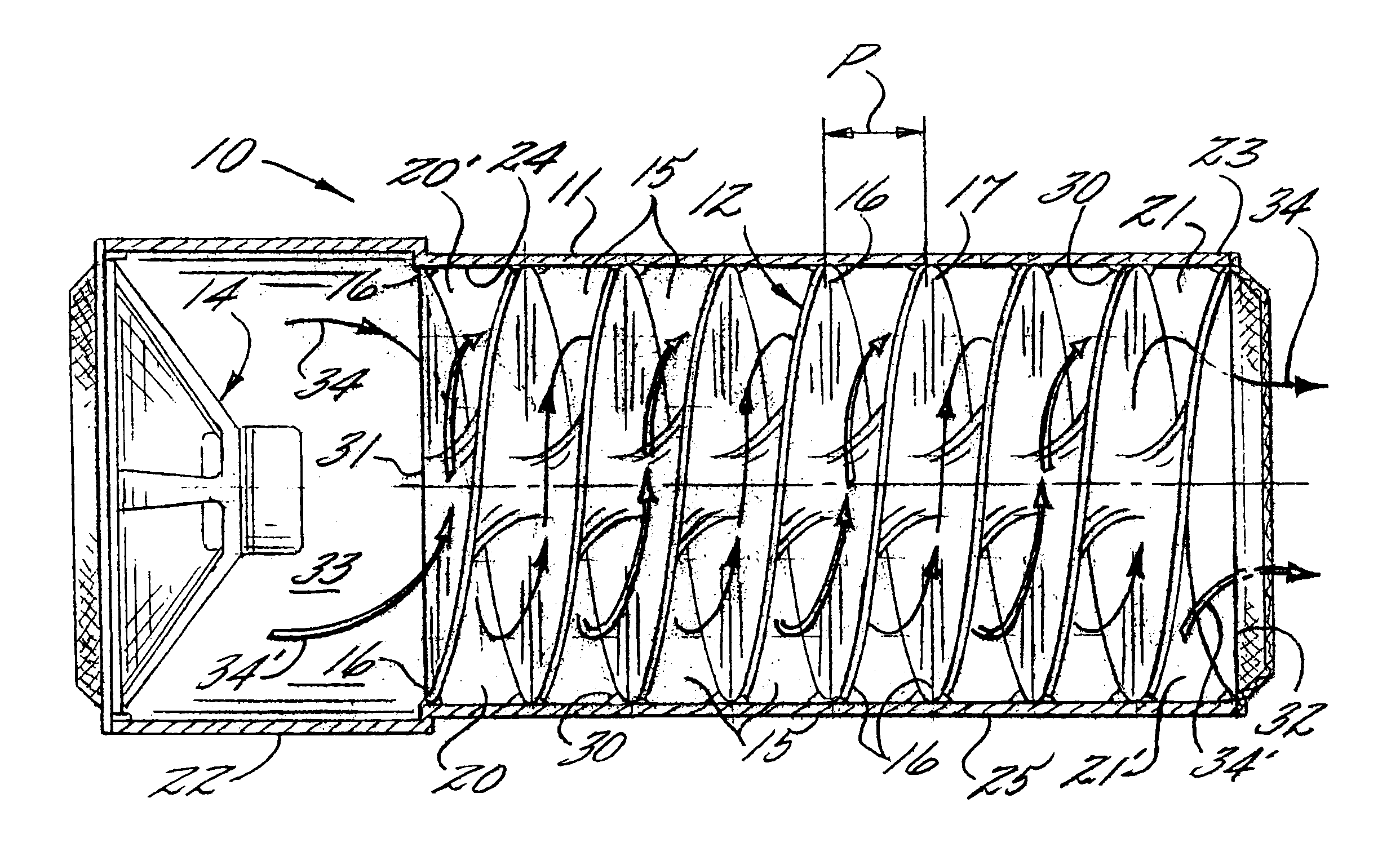
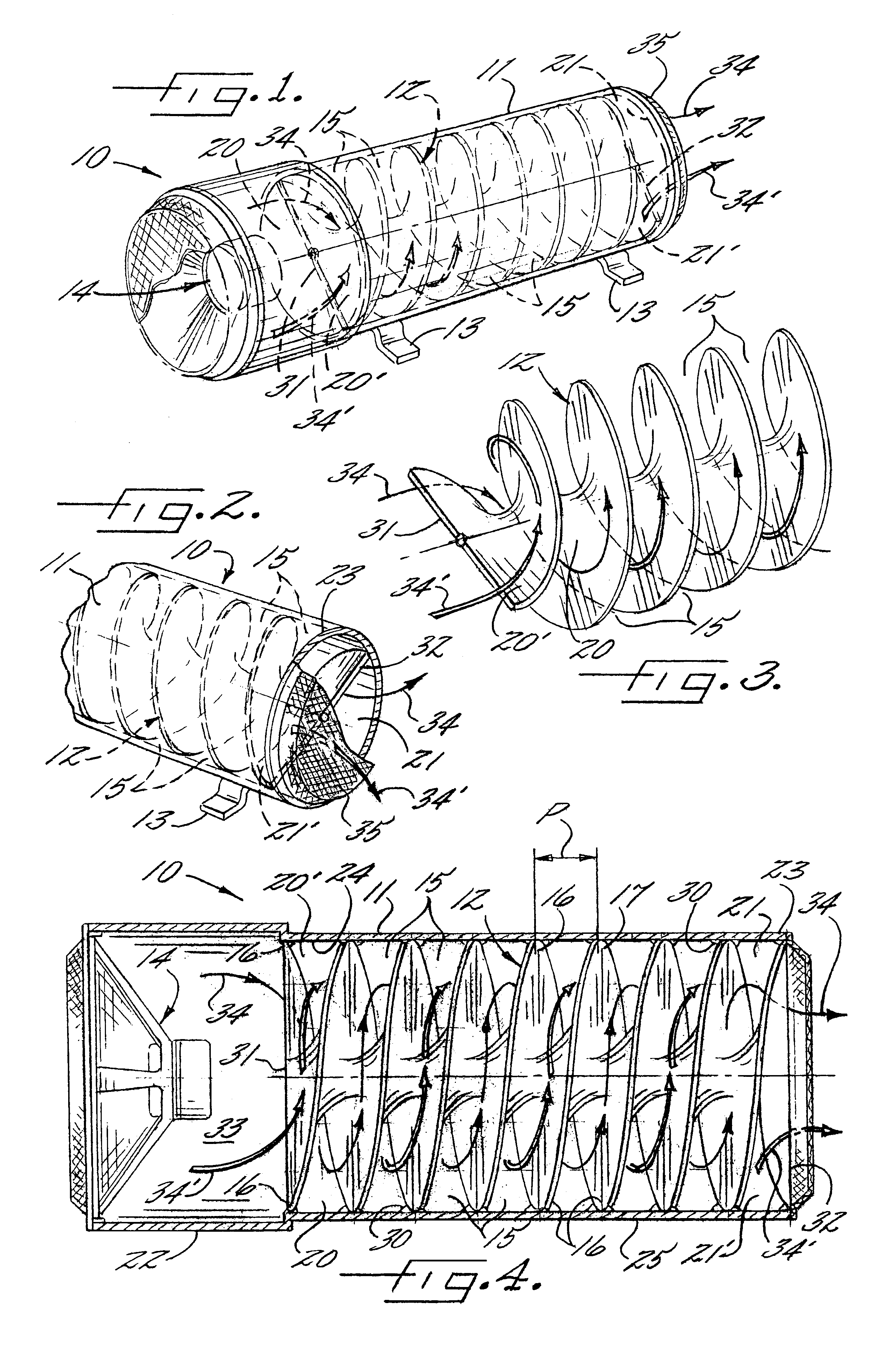
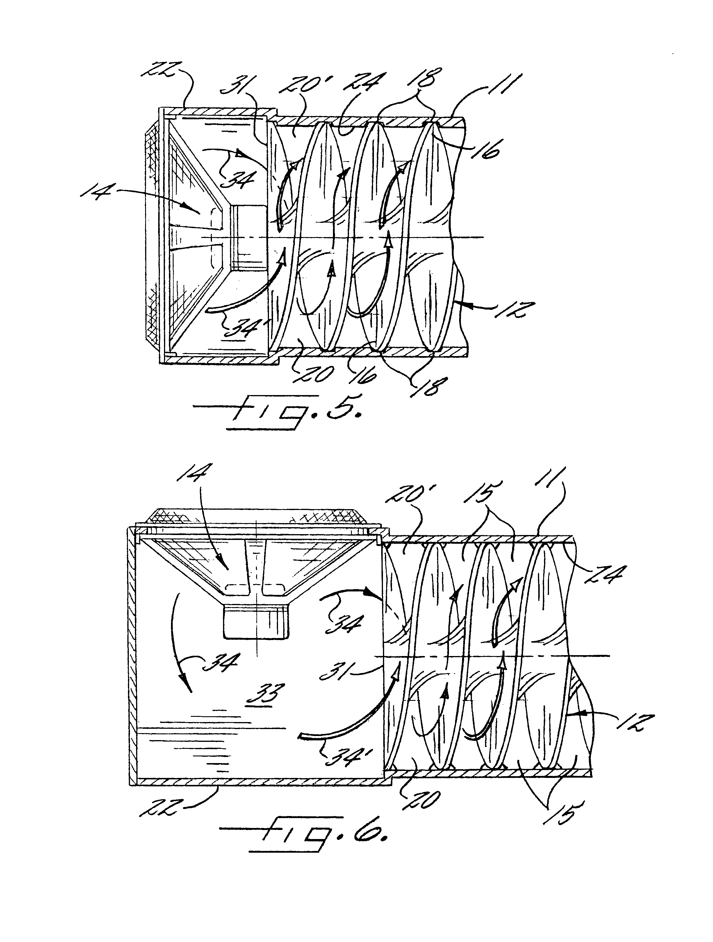
[0025]It will be understood that as used herein the term the term “acoustic path” refers to a passage that directs acoustic waves.

[0026]The term “damping” as used herein refers to the reduction of movement of...


PUM


Abstract

An apparatus for increasing the quality of sound from an acoustic source comprises in one embodiment a hollow enclosure, an acoustic source, an acoustic guide, a pair of acoustic inlet openings, a pair of acoustic exit openings, and pair of acoustic paths, wherein the acoustic inlet openings separate acoustic waves from the acoustic source and direct the acoustic waves the length of the acoustic paths to the acoustic exit openings in such a manner as to increase the quality of sound, and especially bass sound, from the acoustic source.

Description

FIELD OF THE INVENTION[0001]The invention relates to an enclosure for an acoustic source. In particular, the invention relates to an apparatus for increasing the quality of sound from an acoustic source, and that is particularly suited for improving acoustic output of bass sounds.BACKGROUND OF THE INVENTION[0002]Acoustics technology, and in particular stereo technology, has advanced to meet the demand for improved sound quality. The rising popularity in home theater systems and related sound technologies has refocused the stereo industry towards improved and more efficient sound systems. Sound systems are also an integral part of vehicles of all types. Advances in acoustics and electronics technology have resulted in smaller and more efficient delivery systems. Nevertheless, acoustic principles demand relatively lengthy transmission lines or acoustic paths. For example, known acoustic paths may extend up to several feet. Space restrictions in houses, vehicles, and mobile stereos, ho...

Claims


Application Information

Patent Timeline
IPC IPC(8): H04R1/00
CPCH04R1/00
Inventor MACKIN, IAN J.WEIR, WILLIAM L.
Owner CORTECH
Why Eureka
Try Eureka