Compound optical and electrical conductors, and connectors therefor

a technology of optical and electrical conductors and connectors, which is applied in the direction of lighting and heating apparatus, instruments, and fiberoptic cables or rods, which can solve the problems of no motivation for installing any structure within the hollow core, no connection of multiple lengths of such a light transmission line together, and provided for radial light emission from the length of the fiberoptic cor

Inactive Publication Date: 2005-12-13
PLASTICS INVENTIONS & PATENTS INC
View PDF1 Cites 34 Cited by
  • Summary
  • Abstract
  • Description
  • Claims
  • Application Information

AI Technical Summary

Benefits of technology

[0038]It is an object of the invention to provide improved elements and arrangements thereof in an apparatus for the purposes described which is inexpensive, dependable and fully effective in accomplishing its intended purposes.

Problems solved by technology

In any event, these compound devices of the prior art have been intended for axial light and electrical transmission, and have not provided for radial light emission from the length of the fiberoptic core.
Laursen et al. make no suggestion or teaching whatsoever that this hollow core may be used for any other purpose, and thus there is no motivation for installing any structure within the hollow core.
Also, Laursen et al. does not disclose any connection of multiple lengths of such a light transmission line together, nor any radical light output from his light pipe.
Moreover, no inclusion of electrical wiring with the fiberoptic strands is disclosed by Swemer, nor is any means of connecting such compound cables, or even lengths of fiberoptic cables alone, disclosed.
However, no combining of electrical and fiberoptic line is disclosed, nor is any means of connecting a series of such lines disclosed.
Moreover, no connecting means is provided by Gareis et al. for their cable.
However, no inclusion of electrical conductors is provided, nor is any means of connecting a series of such optical conductors disclosed in the '948 U.S. Patent.
However, Kingstone et al. do not describe any means of including electrical wiring with their fiberoptic cable.
Moreover, as the Reilly et al. inline skate fiberoptic device is relatively short, no means of connecting a series of such devices together is disclosed.
However, the fiberoptic components of each embodiment are encased in opaque sheaths or jackets, and / or surrounded by other opaque structure, so that no lateral light emission is possible.
However, as in the case of the cable of the '427 British Publication noted above, the '824 cable does not provide for lateral or radial emission of light from the cable.

Method used


Image

  • Compound optical and electrical conductors, and connectors therefor
  • Compound optical and electrical conductors, and connectors therefor
  • Compound optical and electrical conductors, and connectors therefor

Examples


first embodiment

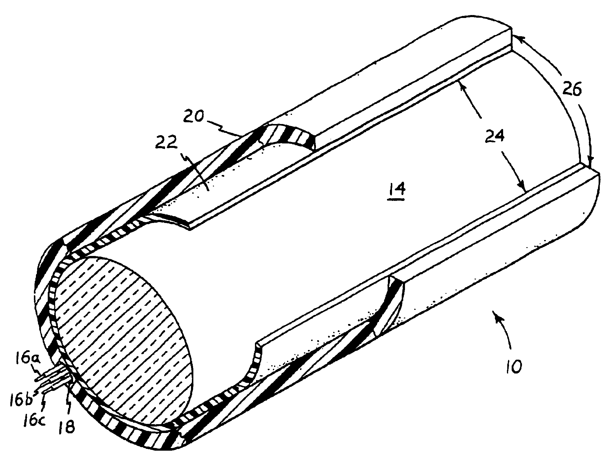
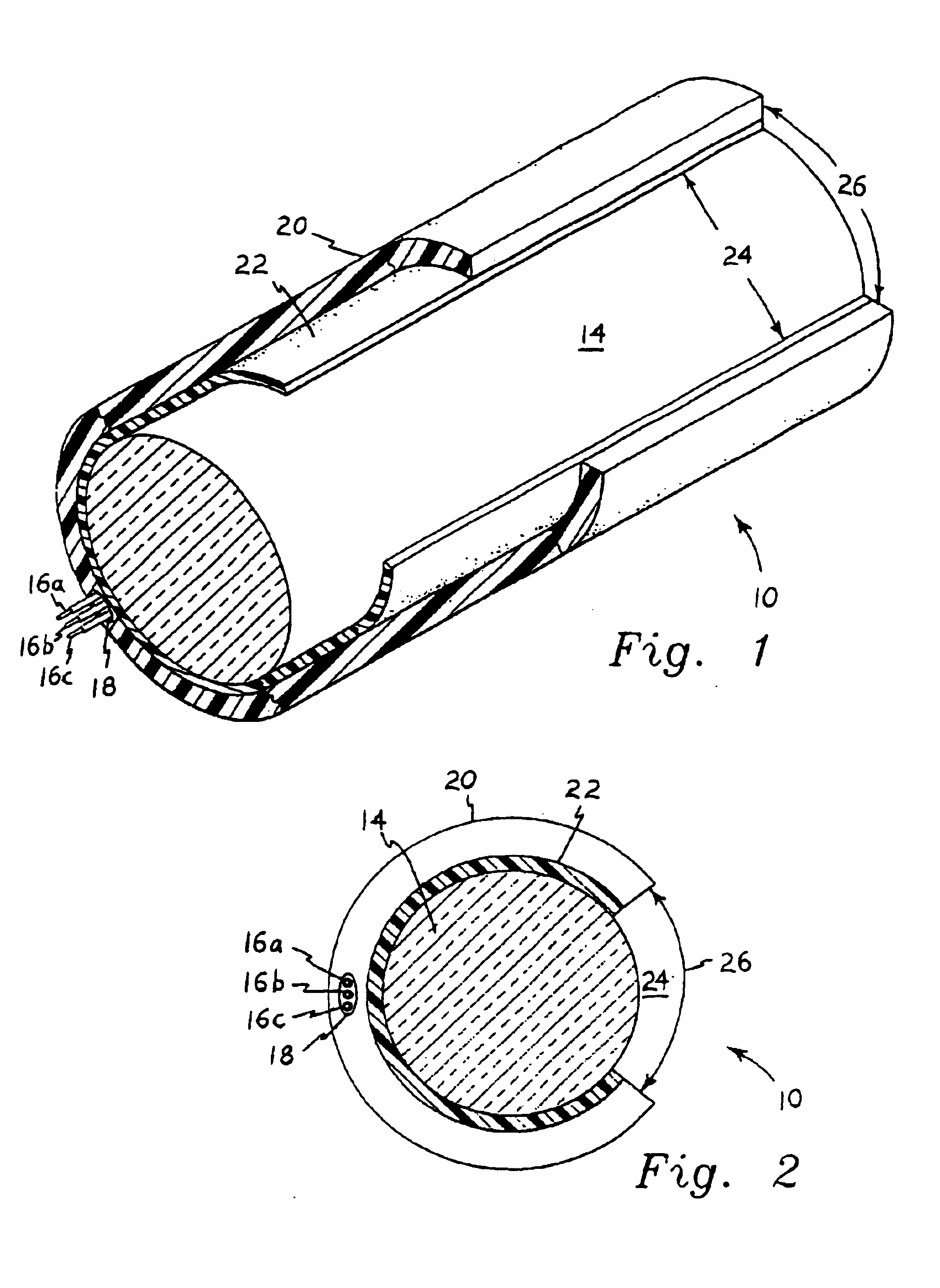
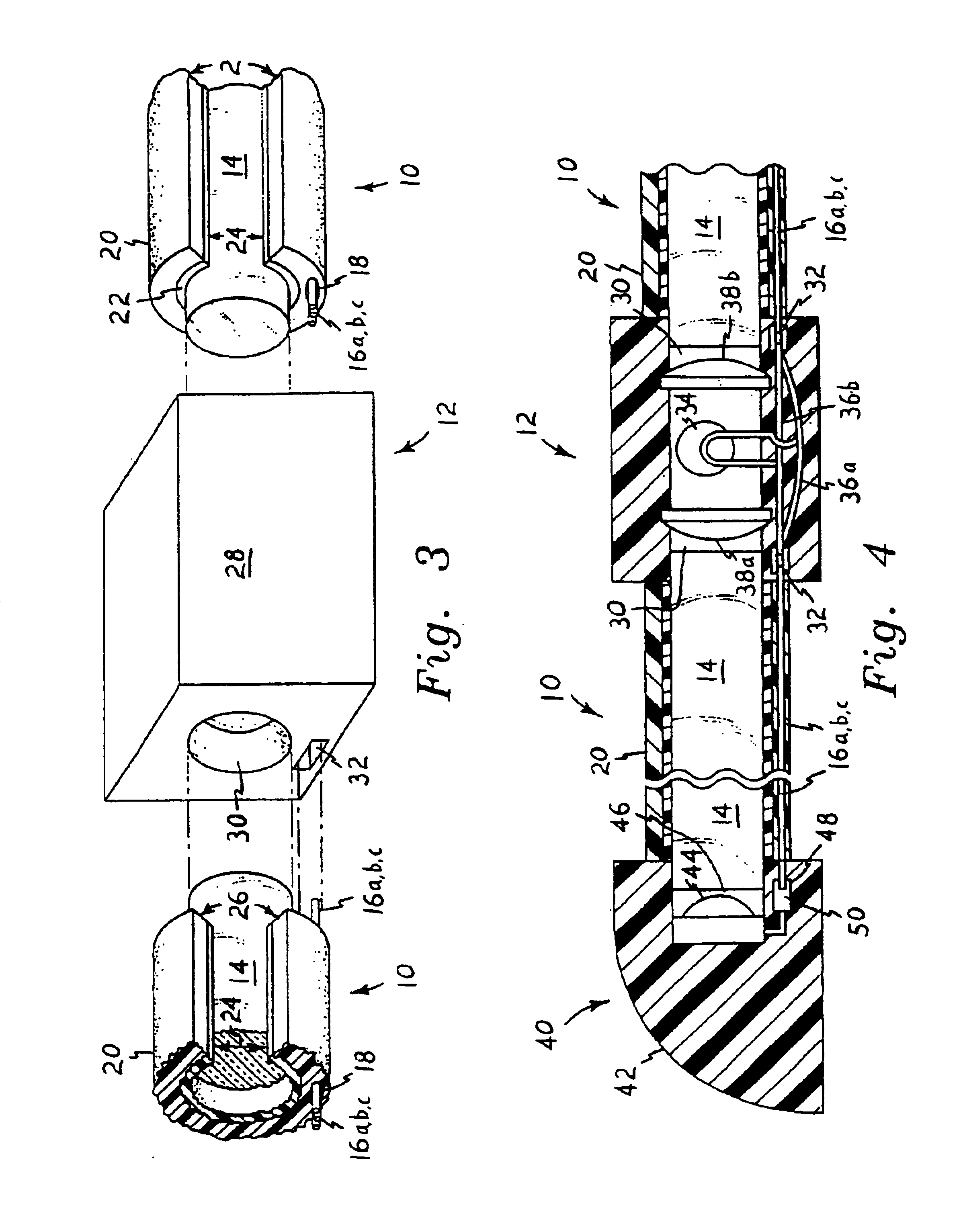
[0058]FIGS. 1 through 4 illustrate the present invention, comprising a compound optical and electrical conductor 10 and cooperating connector 12 (shown in FIGS. 3 and 4). The larger mass and volume of the conductor 10 comprises a light transmitting element 14 (conventional fiberoptic cable formed of a plurality of individual fiberoptic strands, or one or more large diameter, solid core elements, as shown). The use of solid acrylic plastic material for the optical conductor element 14 precludes any requirement for ultraviolet protection, as necessary for other materials specially formulated for light transmission.

[0059]One or more electrical conductors, e.g., conductors 16a through 16c of FIGS. 1 through 4, extend through a passage 18 formed in the opaque polymer outer jacket or protective sheath 20 of the conductor assembly 10. It will be noted that only a single electrical conductor is required where all connector lighting is to be actuated simultaneously, and the assembly is elect...

embodiment 100

[0073]The retainer or track 112 of the compound conductor embodiment 100 of FIGS. 5 through 8 is configured somewhat like the jacket or cover 20 of the compound conductor of FIGS. 1 through 4, in that retainer 112 surrounds the majority of the optical conductor 104, with a relatively narrow light emitting passage 122 formed longitudinally along one side thereof. This limits the light output to an arc defined by the optically open passage 122, in a manner similar to that of the optically open passage 24 of the jacket 20 of the embodiment of FIGS. 1 through 4. Alternatively, the retainer 112 may be formed of a transparent or translucent material (plastic, etc.), as shown in FIG. 6 of the drawings, thus providing a wider arcuate light output therefrom. The arcuate light passage opening 122 of the retainer 112 also provides access for the installation of the optical conductor 104 therein.

[0074]A cooperating compound connector 102 for the optical conductors 100 is illustrated in FIGS. 7 ...

second embodiment

[0076]FIGS. 9 and 10 illustrate yet another embodiment of the present compound optical and electrical conductor invention, wherein the compound conductor 200 includes an optical conductor element 202 having a semicircular of D-shaped cross section. This cross sectional shape is well suited for installation within a correspondingly shaped retainer or jacket 112, identical to the generally D-shaped retainer or jacket 112 illustrated in FIGS. 5 through 8 of the drawings for the second embodiment compound conductor 100.

[0077]However, in the embodiment of FIGS. 9 and 10, the first electrical conductors 204a, 204b are imbedded integrally within the body of the optical conductor 202. This may be done at the time of manufacture of the optical conductor 202, by casting or molding the wiring 204a, 204b in place simultaneously with the casting or molding of the optical conductor 202. Preferably, the electrical conductors or wiring 204a, 204b are positioned well away from the optically exposed ...


PUM

PropertyMeasurementUnit
distanceaaaaaaaaaa
lengthaaaaaaaaaa
electrical conductoraaaaaaaaaa

Abstract

A compound optical and electrical conductor includes a fiberoptic light transmitting element (multiple fibers or single solid rod) with at least one solar cell with LED therewith. The electrical conductor or conductors may be imbedded or otherwise secured within the optically conducting element or its surrounding jacket or sheath, or may be contained in a separate elongate retainer which may be provided to hold the optically conducting element in place as desired. The conductors may include a jacket or retainer which is optically open along one side thereof, allowing the optical conductor to emit light laterally therefrom subtending an angle defined by the optical gap in the jacket or retainer. One or more compound connectors may be provided, for linking two or more such compound conductors together as desired. The connectors provide for both the concentric alignment of the optical conductors, and also the electrical connection of the electrical conductors of the compound devices. The connectors preferably each include one or more lighting elements (halogen, high output LED, etc.) to compensate for light attenuation along the lengths of the attached optical conductors. The electrically conducting elements of the compound conductors provide electrical power to the lighting elements enclosed within the connectors, to provide an increase in light power at points along the length of an assembly. Different colors of lights may be provided, with the electrical conductors providing for the selective illumination of each as desired.

Description

REFERENCE TO RELATED PATENT APPLICATION[0001]This application is a continuation in part of and claims the benefit of U.S. patent application Ser. No. 09 / 670,576 filed Sep. 27, 2000 now U.S. Pat. No. 6,577,794 which is incorporated herein by reference. This application is also a continuation in part of copending U.S. patent application Ser. No. 10 / 385,439 filed Mar. 12, 2003 entitled “Illuminated Guard Rail” which is incorporated herein by reference and claims benefit of provisional application No. 60 / 363,607, filed Mar. 12, 2002.BACKGROUND OF THE INVENTION[0002]1. Field of the Invention[0003]The present invention relates generally to the field of fiberoptic light transmission, and more specifically to fiberoptic or acrylic cables or rods having electrically conductive elements included therewith. A means of electrically and optically connecting a series of individual lengths of such fiberoptic and electrically conductive elements is also disclosed herein.[0004]2. Description of the ...

Claims


Application Information

Patent Timeline
Patent Type & Authority Patents(United States)
IPC IPC(8): E01F15/04G02B6/00G02B6/32G02B6/38
CPCE01F15/0453G02B6/00G02B6/32G02B6/3817
Inventor CURRIE, ROBERT M.ROBERTSON, JONAS J.
Owner PLASTICS INVENTIONS & PATENTS INC
Why Eureka
Try Eureka