Measurement of subterranean lithology using electromagnetic energy

a technology of electromagnetic energy and subterranean lithology, which is applied in the direction of material magnetic variables, using reradiation, instruments, etc., can solve the problems of limited resolution of measurements, inconvenient use of existing logging tools, and insufficient penetration of geologic formation surrounding the borehole, etc., to achieve high resolution, increase electromagnetic energy penetration, and retard energy dissipation

Inactive Publication Date: 2005-12-13
AMINI BIJAN K
View PDF10 Cites 14 Cited by
  • Summary
  • Abstract
  • Description
  • Claims
  • Application Information

AI Technical Summary

Benefits of technology

[0009]This invention pertains to a method and apparatus for measuring the subterranean lithology using Electromagnetic energy. The invention is applicable to the measurement from within uncased boreholes, i.e., open-holes. Also combined within the invention is Magnetic Lenses™ focus and Magnetic Antenna™ transmitter-receptor. These facilitate the present invention achieving increased penetration of electromagnetic energy into the geologic formation from the borehole with high resolution and the ability to control the direction in which the measurements are taken. The invention teaches a method and apparatus for concentrating magnetic flux to retard the dissipation of energy penetrating through the ground formation. The invention utilizes the Magnetic Antenna transmitter-receptor and Magnetic Lensing focus that counter the rapid dissipation of electromagnetic energy.
[0011]The invention utilizes inductive magnetic coupling. Accordingly, the detection apparatus does not need to be in physical contact with the ground or geologic formation. The invention utilizes inductive magnetic coupling to measure the changes in resistivity within the geologic formation that signal the presence of material having different electrical properties. The apparatus measures and records the electromagnetic properties of the geologic structure comprising the formation, e.g., limestone, granite, etc., and materials occupying the interstices of the geologic formation, e.g., water, hydrocarbon, etc. The invention transmits magnetic flux into the formation. This provides information regarding the electrical resistivity and lossiness of the formation. This provides information regarding the constituent matter within the formation. The measurements may be taken at various depths or locations within the subsurface penetrated by the borehole by the transmission of oscillating magnetic flux. The apparatus can thereby measure and record the location and amplitude of said resistivity in single or multiple directions, and at distances that facilitate locating electrically conductive materials. Examples of materials of interest having low conductivity are hydrocarbon gases or liquids. The other common media located within the interstices of a geologic formation is water or salt water. Water and particularly salt water have significantly higher electrical conductivity than hydrocarbons. Therefore measuring the electrical resistivity of geologic formations can provide reliable information regarding the substance located within a particular formation. The invention is not, however, limited to detection of hydrocarbon and water. The fact that the invention does not require physical contact with the surface of the geologic formation greatly facilitates movement of the detection apparatus. It also minimizes the wear upon the detection apparatus housing and other components.
[0013]Each bistatic magnetic flux transmitter / receiver array incorporates one or more EM barriers. As used herein, an “EM barrier” or “barrier material” can be any electrically conductive and magnetically permeable material such as carbon steel. The combined components form a Magnetic Antenna™ transmitter-receptor. The magnetic saturation flux generator, transmitter and receiver components are electrically insulated from the EM barrier. By partially saturating the EM barrier, an electrically conductive and magnetically permeable material, the EM barrier will more readily engage with higher frequency oscillating transmitter flux. By well-known electromotive forces, the oscillating magnetic flux induces eddy currents with the barrier. This separate oscillating electromagnetic current generates a separate magnetic flux that is broadcast out of the barrier and into the geologic formation, thereby causing the EM barrier to be a magnetic antenna.
[0014]By controlling the quantity of the magnetic saturation flux of the magnetic saturation generator, the relative permeability of the antenna can be controlled. As the permeability of barrier material comprising the antenna is lowered, more oscillating transmitter flux penetrates into the antenna, creating greater eddy currents and resulting in increased oscillating flux broadcast from the length of the antenna. Further, the lowered relative permeability of the antenna alters the shape of the oscillating flux field generated by the eddy currents and transmitted out from the antenna. This allows the flux to be focused. By focusing the flux, an increased density of oscillating flux can be created at greater distances from the apparatus that otherwise has been previously possible. This counters the typical dispersion of flux as it is transmitted away from the antenna. It permits measurements being made at greater distances into the formation than previously achievable. The increased density of flux also increases the resolution of measured property. This focusing of the magnetic flux, with the resulting enhanced penetration into the formation and with high resolution, is termed Magnetic Lensing focus.
[0015]To enhance the reception of the separate magnetic flux (“receiver signals”) induced within electrically conductive material existing with the area of the geologic formation targeted for measurement, a receiver is also located proximate to the transmitter and magnetic saturation generator (a monostatic configuration) and, alternatively, with a separate magnetic saturation generator (a bistatic configuration).

Problems solved by technology

Existing logging tools can not provide the adequate penetration into the geologic formation surrounding the borehole.
In addition, existing logging tools are not directional.
The resolution of measurements is also limited, particularly at greater distances into the geologic formation.
The depth into geologic formations that existing tools, utilizing electromagnetic energy and located in a single borehole, can measure is limited by the separation between the transmitter and receiver for the electromagnetic energy.
Further, a fixed separation distance limits the vertical resolution (assuming the axis of the borehole is vertically oriented) as measurements are attempted further into the formation from the borehole).
However, these electric waves suffer great attenuation when confronted by ground water, clays or other highly conductive media within a geologic formation.
Using focusing antennas with high gain improves the situation only marginally since the amount of gain is usually not enough to offset the amount of loss or attenuation of the electromagnetic energy incurred as the high frequency wave passes through layers of electrically conductive material.
There has not, however, been a high gain magnetic antennas available to focus the magnetic flux in a desired or controlled manner.
The resulting rapid loss of power has substantially limited the effective range of distance that oscillating magnetic flux can be utilized.

Method used


Image

  • Measurement of subterranean lithology using electromagnetic energy
  • Measurement of subterranean lithology using electromagnetic energy
  • Measurement of subterranean lithology using electromagnetic energy

Examples


Embodiment Construction

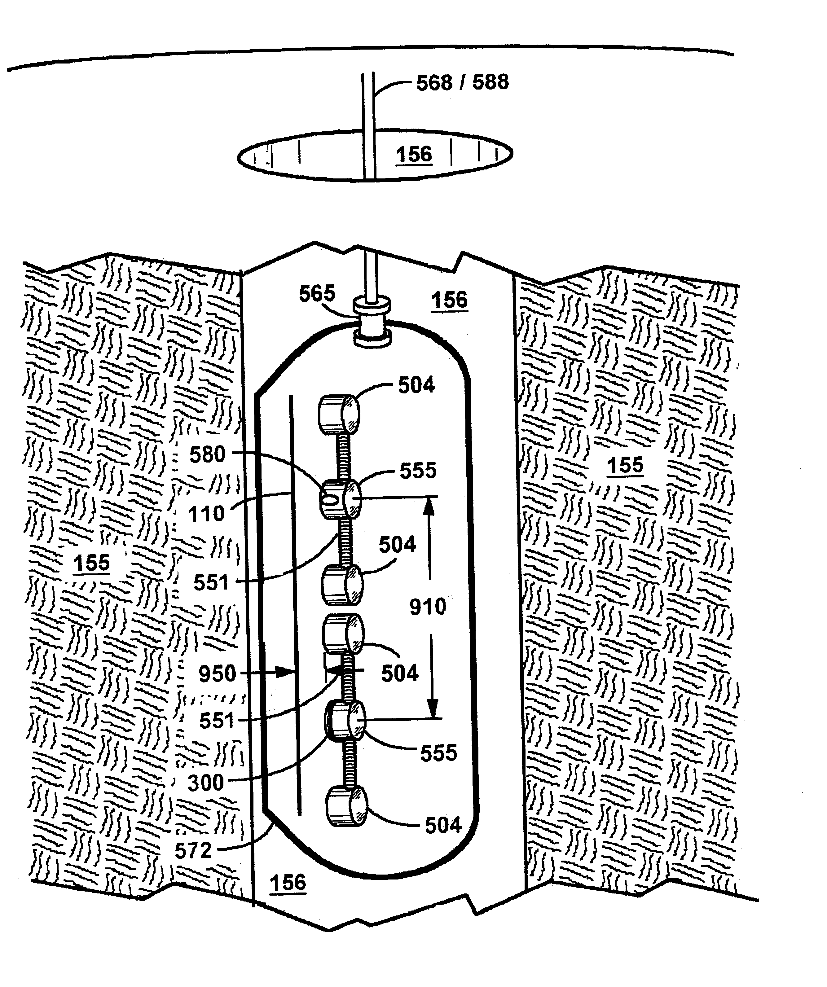
[0065]This invention pertains to a method and apparatus for measuring the subterranean lithology using Electromagnetic energy. The invention is applicable to the measurement from within uncased boreholes, i.e., and open-holes. Also combined into the configuration is Magnetic Lenses™ focus and Magnetic Antenna™ transmitter-receptor. These facilitate the present invention achieving increased penetration of electromagnetic energy into the geologic formation from the borehole with high resolution and the ability to control the direction in which the measurements are taken. The invention teaches a method and apparatus for concentrating magnetic flux to retard the dissipation of energy penetrating through the ground formation. The invention utilizes the Magnetic Antenna transmitter-receptor and Magnetic Lensing focus that counter the rapid dissipation of electromagnetic energy.

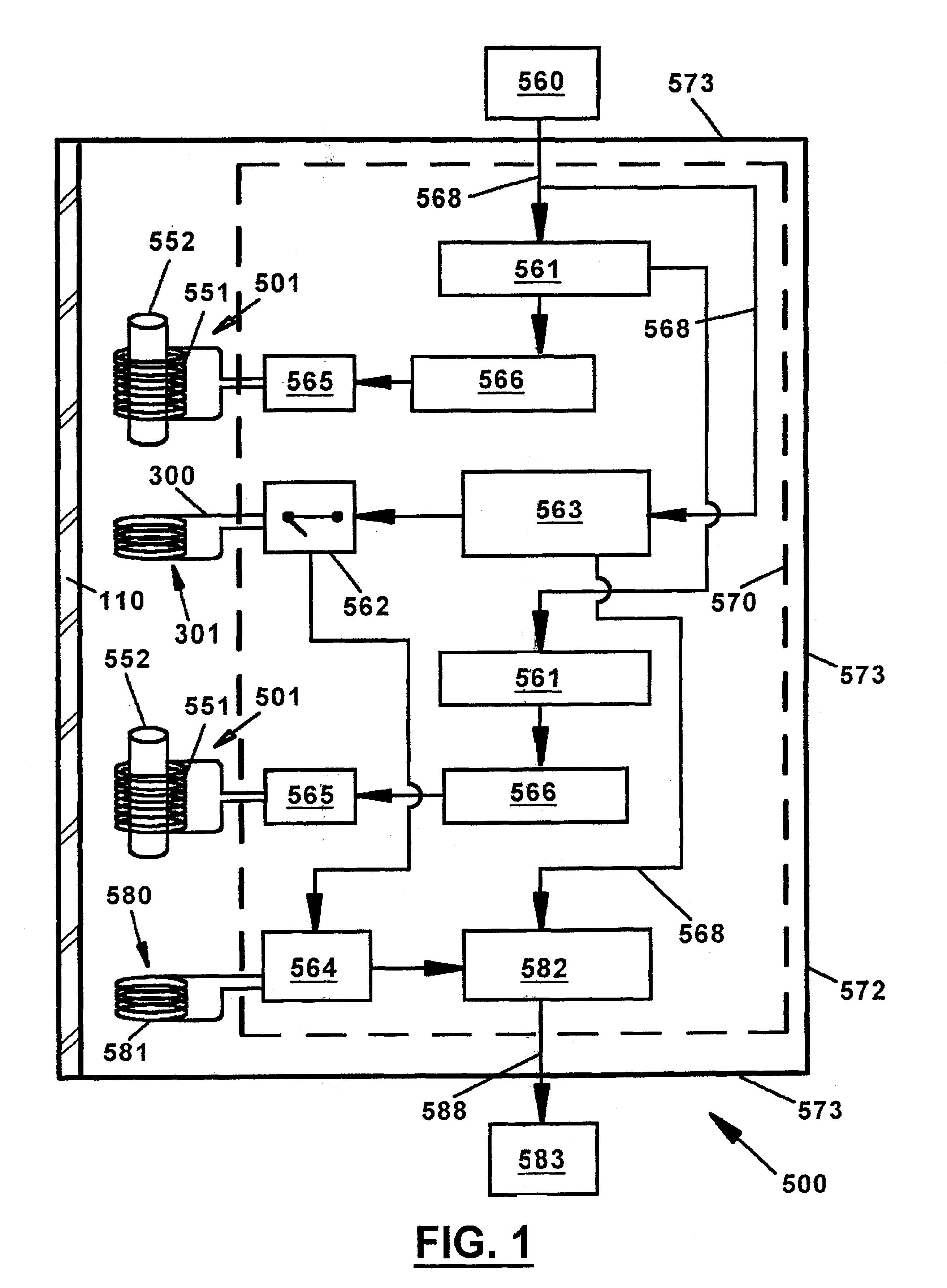
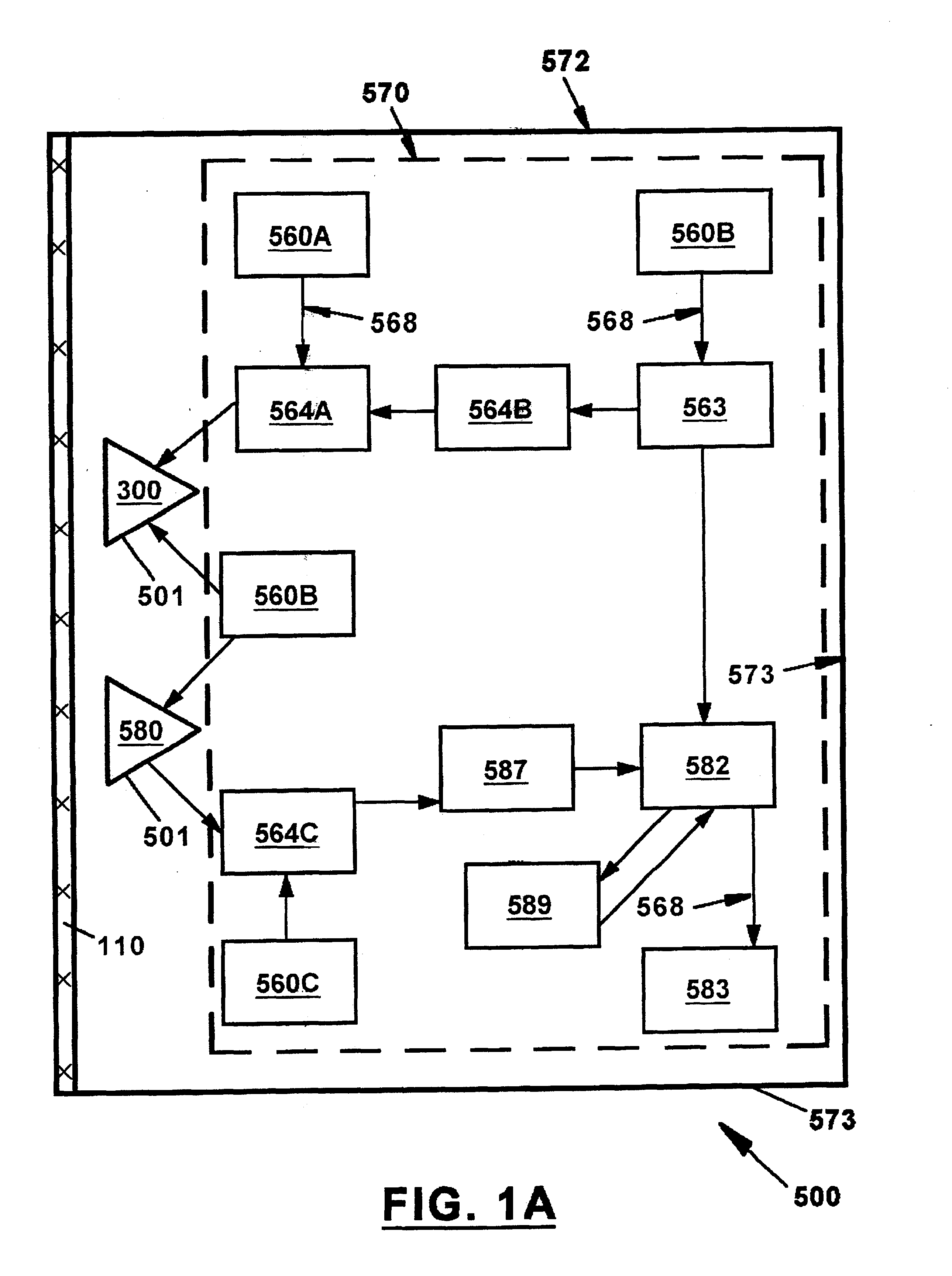
[0066]The invention may utilize one or more monostatic or bistatic configurations of magnetic flux transmitters a...


PUM


Abstract

The invention subject of this application pertains to a method and apparatus for measuring the subterranean lithology using electromagnetic energy. The invention is applicable to the measurement from within uncased boreholes, i.e., and open-holes. The present invention transmits and receives electromagnetic energy deep into a geologic formation from a borehole, while also providing high resolution for distant measurements and the ability to control the direction in which the measurements are taken. The invention does not require a receiver to be located at the ground surface or in another borehole. In simple terms, the apparatus of this invention is able to “look around” into the surrounding geologic formation from a stationary position.

Description

CROSS REFERENCE TO RELATED APPLICATION[0001]This application claims the benefit of and priority to U.S. Provisional Application No. 60 / 285,425, entitled “Openhole Logging Tool” and filed Apr. 21, 2001.BACKGROUND OF INVENTION[0002]1. Field of Use[0003]The invention subject of this application pertains to a method and apparatus for measuring the subterranean lithology using electromagnetic energy. The invention is applicable to the measurement from within uncased boreholes, i.e., and open-holes. The present invention transmits and receives electromagnetic energy deep into a geologic formation from a borehole, while also providing high resolution for distant measurements and the ability to control the direction in which the measurements are taken. The invention does not require a receiver to be located at the ground surface or in another borehole. In simple terms, the apparatus of this invention is able to “look around” into the surrounding geologic formation from a stationary position...

Claims


Application Information

Patent Timeline
Patent Type & Authority Patents(United States)
IPC IPC(8): G01V3/28
CPCG01V3/28
Inventor AMINI, BIJAN K.
Owner AMINI BIJAN K
Why Eureka
Try Eureka