Method and apparatus for tracking remote ends of networking cables

a technology for networking cables and remote ends, applied in the direction of identification means, coupling device connections, instruments, etc., can solve the problems of additional costs, labor intensive and expensive process, and further service problems, and achieve the effect of ensuring the traceability of networking cables

Inactive Publication Date: 2005-12-13
BROWN ALAN J
View PDF14 Cites 72 Cited by
  • Summary
  • Abstract
  • Description
  • Claims
  • Application Information

AI Technical Summary

Benefits of technology

[0008]The present invention provides a method and apparatus for readily tracing networking cables. A networking cable having features of the present invention comprises a plurality of copper wire pairs encased in a flexible sheath for effectuating transmissive interconnections, electrically activated telltales affixed to both ends of the cable for providing an identification signal when activated, and means for selectively applying a current to the cable that activates the telltales. A power pack may be provided for applying a current through the electri

Problems solved by technology

Tracing and identifying a remote connector section or end of a specific cable for changing its connection in a network or to facilitate replacement often is difficult, tedious and time consuming, and can lead to errors which create further service problems and additional costs.
This process may be labor intensive and expensive

Method used


Image

  • Method and apparatus for tracking remote ends of networking cables
  • Method and apparatus for tracking remote ends of networking cables
  • Method and apparatus for tracking remote ends of networking cables

Examples


Embodiment Construction

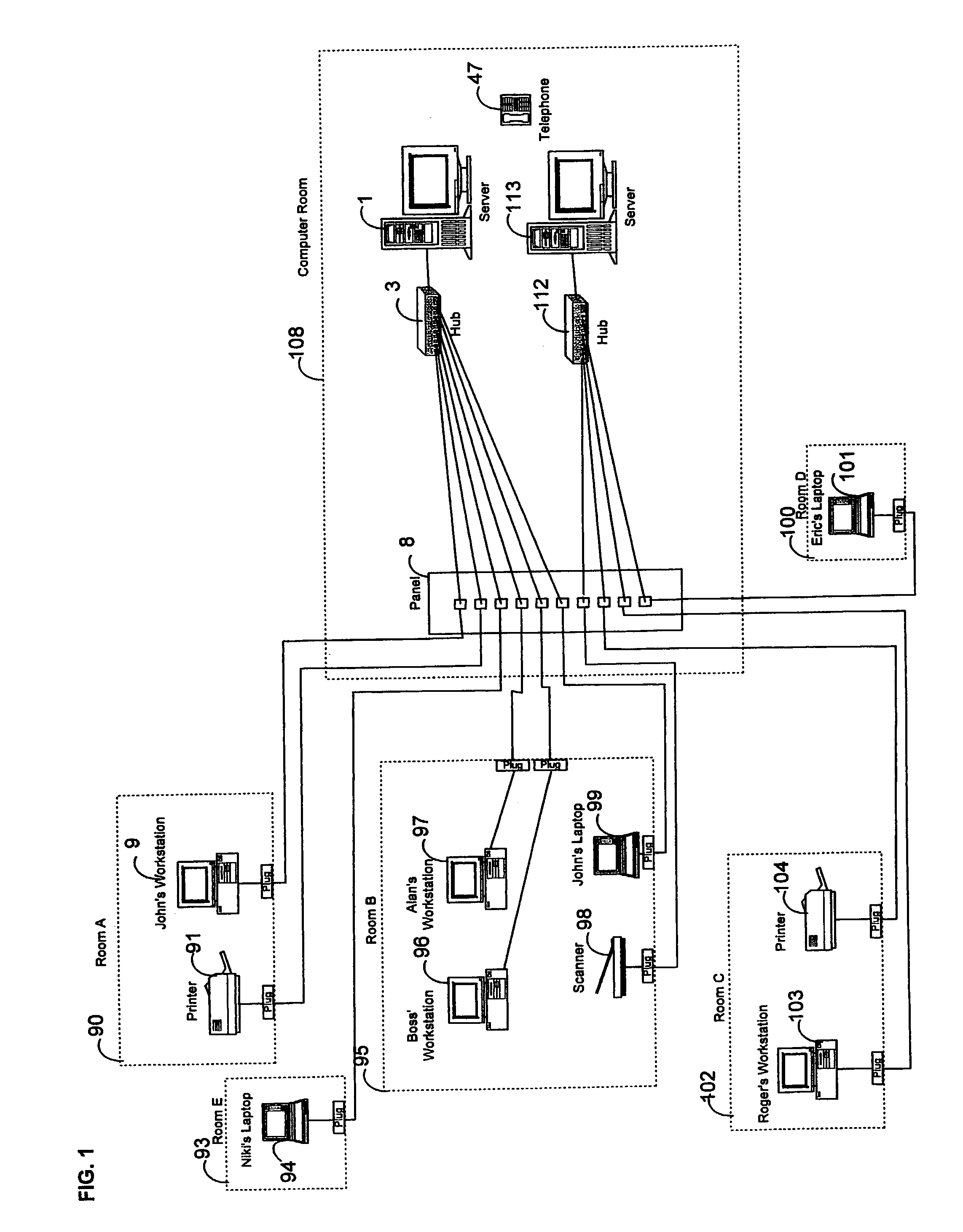
[0020]FIG. 1 illustrates a typical multiple computer environment which includes a plurality of computer workstations 9, 96, 97 and 103, computer laptops 94, 99 and 101, and peripheral devices 91, 98, and 104 linked by networking cable to data hubs 3 and 112 and computer servers 1 and 113. Typically, a computer room 108 houses the computer servers 1 and 113 and data hubs 3 and 112 of the computer network. Located separately, such as in room A 90, room B 95, room C 102, room D 100, and room E 93, are the computer workstations and the various devices of network. Devices include computer equipment, printers, scanners, and terminals. Between the computer workstations 9, 96, 97, and 103 and the servers 1 and 113 is a workstation panel 8 that holds the networking cable. The workstation panel may be located in the computer room 108 or may be located in a separate location such as what is known as a “closet.” From the workstation panel 8 networking cable is used to connect the computers 9, 9...


PUM


Abstract

This specialized networking cable includes a plurality of twisted copper wire pairs encased in a flexible sheath for effectuating transmissive interconnections, electrically activated telltales affixed to both ends of the cable at positions adjacent to and connected to at least one of the copper wire pairs for providing an identification signal when activated; and means for selectively applying a current to the cable that activates the telltales and does not interfere with the flow of data through the cable whereby the telltales may be activated on at least one of the twisted copper pairs. An LED and an electric power connector suitable for plug-in connection of a power pack are affixed to the cable adjacent each end such that both LEDs are lighted whenever power is applied to either of the electrical connectors. The attendant illumination of the LEDs readily indicates where both ends of the networking cable are located. The networking cable also may be used for convenient telephonic communication by service personnel. One embodiment includes the cable as described above except with one end having a connector mateable with a standard Category 5 networking cable thereby providing for a standard networking cable to be converted into a specialized networking cable usable for tracing cable ends.

Description

[0001]This application is a continuation of U.S. patent application Ser. No. 09 / 460,775 filed on Dec. 14, 1999 now U.S. Pat. No. 6,577,243, the entire contents of which arc hereby incorporated by reference.FIELD OF THE INVENTION[0002]This invention relates to a method and apparatus for readily tracing remote connective portions of networking cables. It also provides a means for visually identifying the cabling from a computer workstation to a workstation panel and to a hub that connects the computer workstation to a server. This invention also includes a circuit that allows a light emitting diode (LED) to be connected across two pairs of interconnecting wire cable without disrupting those pairs for carrying data between the server and the workstation.BACKGROUND OF THE INVENTION[0003]The purpose of any networking cable is to carry data from one computer-related device to another. Computer-related devices include terminals, personal computers, printers, workstations, hubs, switches, s...

Claims


Application Information

Patent Timeline
IPC IPC(8): G01R31/02H01R13/641H01R13/66H01R13/717
CPCH01R13/641H01R13/6641H01R13/717H01R13/7175G01R31/023H01R13/7177G01R31/60H01R31/065
Inventor DANNENMANN, JOHNHELGERSON, RONALD
Owner BROWN ALAN J
Why Eureka
Try Eureka