Information processing apparatus and information processing method

a technology of information processing and information processing equipment, which is applied in the direction of digital output to print units, instruments, digitally marking record carriers, etc., can solve the problems of unsatisfactory user interface, errors, and insufficient efficiency of data preparation process, so as to improve the work efficiency of users and facilitate the preparation of accurate printing data

Inactive Publication Date: 2005-12-13
CANON KK
View PDF15 Cites 49 Cited by
  • Summary
  • Abstract
  • Description
  • Claims
  • Application Information

AI Technical Summary

Benefits of technology

[0028]To resolve the various conventional shortcomings described above, it is a first objective of the present invention to precisely and easily prepare accurate printing data without the work efficiency of a user being deteriorated.
[0029]It is a second objective of the present invention to designate an adequate output color for a reverse video element for which a reverse video attribute is set, and to easily and consistently identify the reverse video element in, for example, an interactive editing process.
[0030]It is a third objective of the present invention to accurately determine the location of a character string.
[0031]It is a fourth objective of the present invention to accurately change the magnification rate for of a figure in association with printing data, without the work efficiency of a user being deteriorated.

Problems solved by technology

However, the above described examples of prior art methods have the following problems, which are assigned numbers that correspond to those provided for the individual examples described above.
(1) Since an image printed by a printer differs considerably from that which is presented on a display device, a user must repeat the printing process many times and repetitiously perform corrections until a desired image is obtained, and further, a satisfactory user interface is not available.
Also, since display data must be prepared in addition to print data, the efficiency of the data preparation process is not fully satisfactory.
Therefore, when an image is produced by a printer that has a resolution that is considerably higher than that of the display device, errors occur because of the difference in the resolutions, and what is provided on the display device differs from the results that are provided by the printer.
Even when the layout of an image on the display device seems correct to a user, small errors occur in the image that is actually printed by a printer having 30 to 50 times the resolution of the display device, and this renders correct position alignment very difficult.
(3) When a markup language, such as a Tex, is employed, unlike method (2) errors error due to a difference in resolution do not occur so long as the correct layout is instructed.
However, since the processing is not performed interactively, a user can not perform a layout operation while observing the results of the layout, so that the user interface is even less satisfactory than is the one in method (1).
Since the layout must always be precisely described, even when a detailed layout is not required, to prepare the printing data extra labor must be expended and the number of unnecessary operations that are performed is increased, and the efficiency of the work performed by a user is deteriorated.
Thus, if the image is modified by enlarging or reducing it, the resultant image becomes jagged and representation accuracy can not be maintained.
In this case, if a string comprising reverse video characters is placed directly on the background, or if the solid color figure that constitutes the background for the reverse video character string, or for a reverse video graphic figure, is moved or deleted during interactive editing processing, the reverse video character string, or figure, can not be distinguished from the background, thus rendering the editing job very difficult.
In this case, when the solid color background figure and the reverse video character string are set to the temporarily specific state at the same time, they can not be distinguished, one from the other, and again the editing job is very difficult.
However, the following conventional problem has arisen.
Furthermore, since the location of a specific character corresponds to a tab position, precise positioning is difficult to achieve.

Method used


Image

  • Information processing apparatus and information processing method
  • Information processing apparatus and information processing method
  • Information processing apparatus and information processing method

Examples


first embodiment

(a) First Embodiment

[Explanation for Hardware Arrangement]

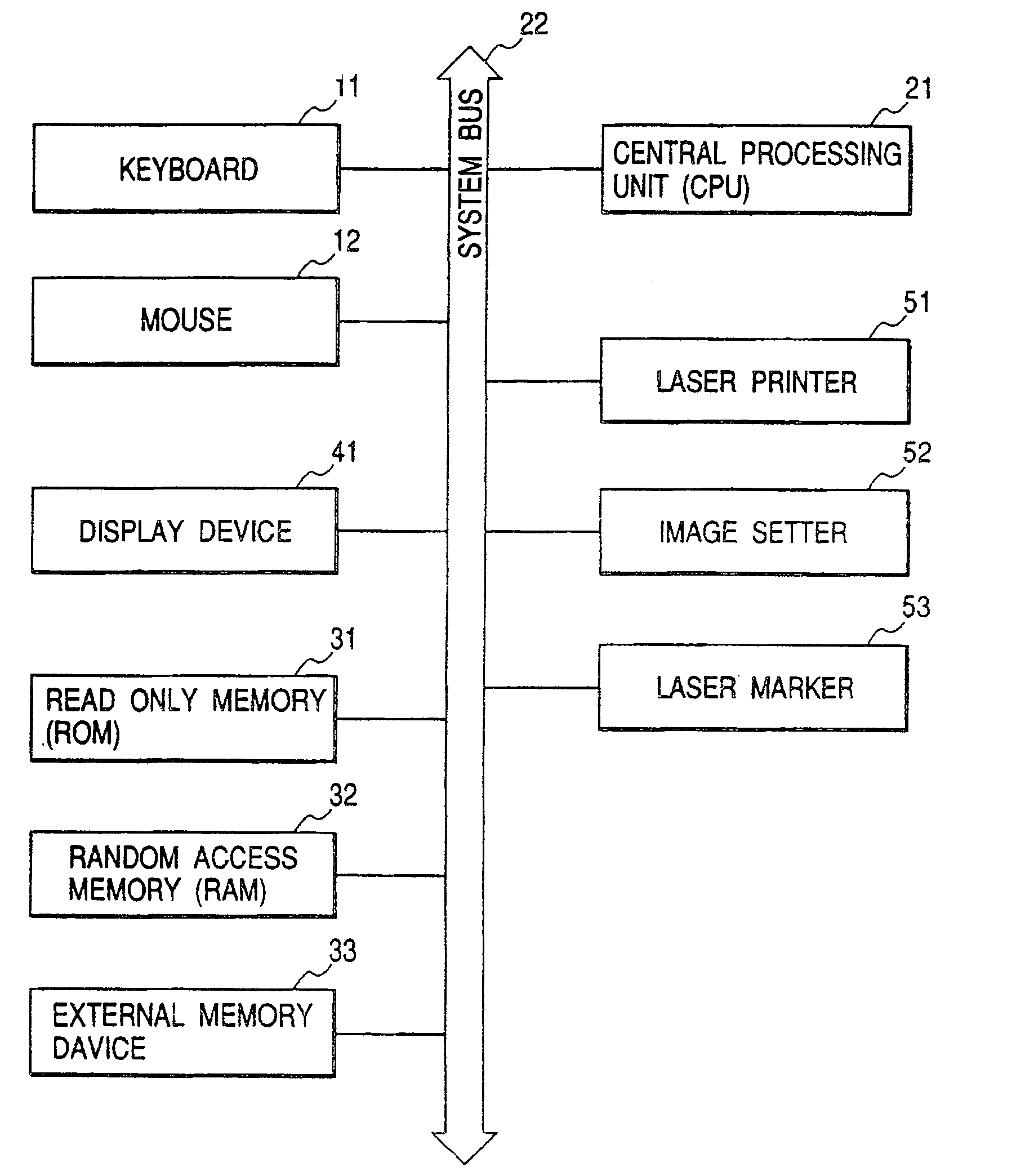
[0248]FIG. 1 is a block diagram illustrating the hardware arrangement of an information processing apparatus according to a first embodiment of the present invention.

[0249]In FIG. 1, a central processing unit (CPU) 21 exercises overall control of the apparatus and performs computation processes. A keyboard 11 is used to input characters and numerical values, and a mouse 12 is used to point to coordinates and to graphic patterns. A display device 41 displays graphic data, character data, and various operation panels and buttons.

[0250]A program according to this embodiment is stored in read only memory (ROM) 31 and is executed by the CPU 21. While executing the program for this embodiment, the CPU 21 reads data from or writes data in random access memory (RAM) 32, as needed. And an external storage device 33 is either a floppy disk device (FD) or a hard disk device (HD) used for the storage of data, such as character typeface i...

second embodiment

(b) Second Embodiment

[1023]In the first embodiment, at step S0901 in FIG. 9, and at steps S3401 and S3402 in FIG. 34, the information is entered that is required for registering the graphic data and the character data as printing data. Instead of performing these steps, graphic data or character data that are prepared in advance by another drawing device may be loaded into the information processing apparatus.

[1024]In this case, the graphic data and the character data that are prepared by another drawing device are converted by the CPU 21 into a form that the information processing apparatus can read. The resultant data are stored in the external storage device 33, and for use are loaded into the RAM 32.

[1025]The data prepared by the drawing device may be transmitted to an external storage device 33, such as a hard disk device connected to the information processing apparatus, and for use the CPU 21 may directly load the received data. Further, the data prepared by another drawing d...

third embodiment

(c) Third Embodiment

[1030]In the first embodiment, at step S2504 in FIG. 25 and at step S3408 in FIG. 34, an explanation has been given for the process for designating the layout positions for the graphic data and the character data. A CAD device may prepare in advance graphic data that is used as a reference for designating the layout positions, and the information processing apparatus of the present invention may load the graphic data.

[1031]In this case, the printing data prepared by the information processing apparatus are to be used to label the drawings of mechanical parts, and the CAD drawing of the mechanical parts can also be displayed in the drawing area 62 for use as a reference when designating the layout positions.

[1032]The graphic data prepared by the CAD device is converted by the CPU 21 into a form that the information processing apparatus can read, and the resultant data are stored in the external storage device 33 and for use are loaded into the RAM 32.

[1033]The gra...


PUM


Abstract

Information that is required for laying out character string data is entered, as are character string data. The printing attributes for the data are then edited, and are employed to extract contour information. Thereafter, the extracted contour information is employed to determine the information that is to be used as a reference when laying out the character string data, and a layout position is specified. Then, the various data that are obtained are stored as printing data, and the character string data are laid out in a drawing area. Therefore, the printing data can be precisely and easily prepared, without the work efficiency of a user being deteriorated.

Description

BACKGROUND OF THE INVENTION[0001]1. Field of the Invention[0002]The present invention relates to an information processing apparatus having an editing function, an information processing method therefor, and a storage medium. The present invention is preferable, for example, for an information processing apparatus and an information processing method for creating very delicate block copy, and a storage medium therefor.[0003]2. Related Background Art[0004]An example information processing apparatus having an editing function is an interactive drawing system, such as a CAD or a DTP (Desk Top Publishing) system, for preparing print data, in particular, printing data for a block copy for graphic patterns, characters and illustrations that are displayed on the main bodies of products or on their external packages, or in manuals. The following methods are conventionally employed by the above system to prepare such print data.[0005](1) A method whereby interactive graphic patterns and char...

Claims


Application Information

Patent Timeline
Patent Type & Authority Patents(United States)
IPC IPC(8): G06T11/20G06T11/60
CPCG06F17/211G06T11/203G06T11/60G06F40/103
Inventor ABE, TOSHIONAMIKI, HIROYUKIKAGEURA, MASARUMIZUKAMI, ATSUSHINAKAGAWA, TAKAHIRONAKANISHI, NAOKIINAHO, KENICHIHORIKAWA, REIKO
Owner CANON KK
Why Eureka
Try Eureka