Scanning optical system
a scanning optical system and optical system technology, applied in the field of scanning optical apparatus, can solve the problems of thermal expansion of scanning, the inability to ignore the change in the refractive index of the scanning lens and the insufficient compensation of the structure disclosed in the above publication, so as to achieve the effect of suppressing the displacement of the focal point due to the temperature change and simple and cost-effective structur
- Summary
- Abstract
- Description
- Claims
- Application Information
AI Technical Summary
Benefits of technology
Problems solved by technology
Method used
Image
Examples
example 1
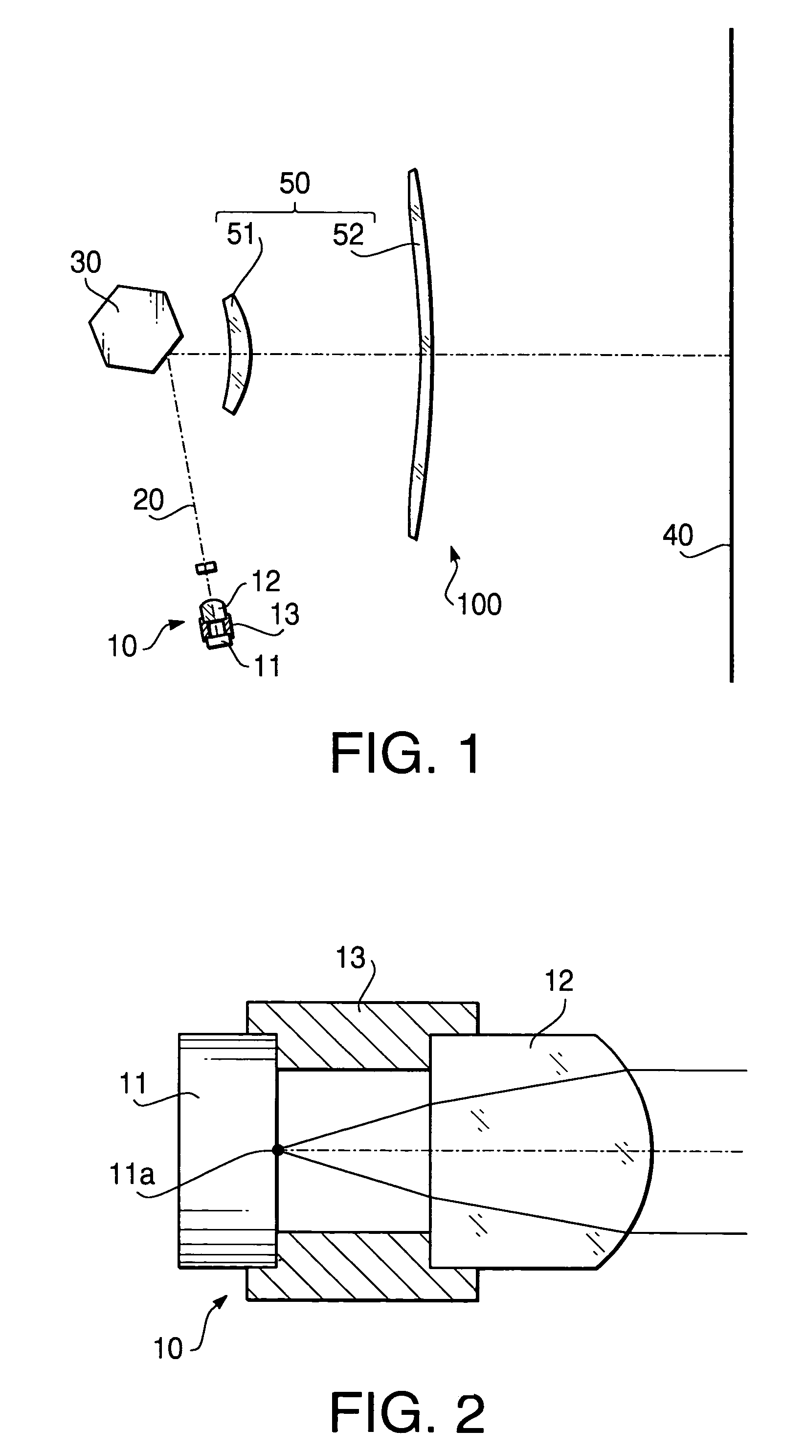
[0036]The collimating lens 12 according to Example 1 is configured as indicated in Table 1. The focal length fc of the collimating lens according to Example 1 is 13.5 mm.
[0037]
TABLE 1radius ofsurfacerefractivecurvaturedistanceindexR1 (light source side)∞10.001.51072R2 (polygonal mirror side)−6.894
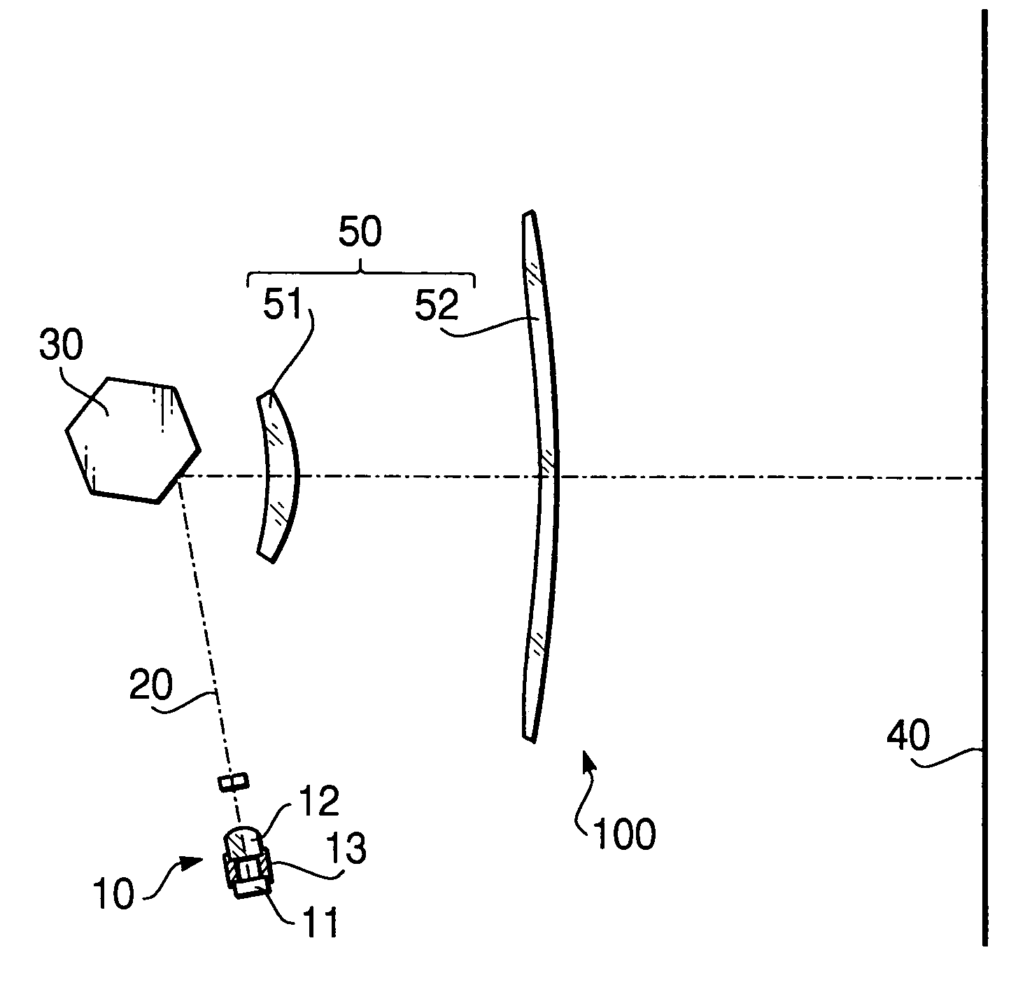
[0038]In Example 1, the linear expansion coefficient α of the support member 13 is 4.50×10⁻⁵, the effective length L of the support member 13 is 6.9 mm, and the focal length f of the scanning lens 50 is 145.0 mm.
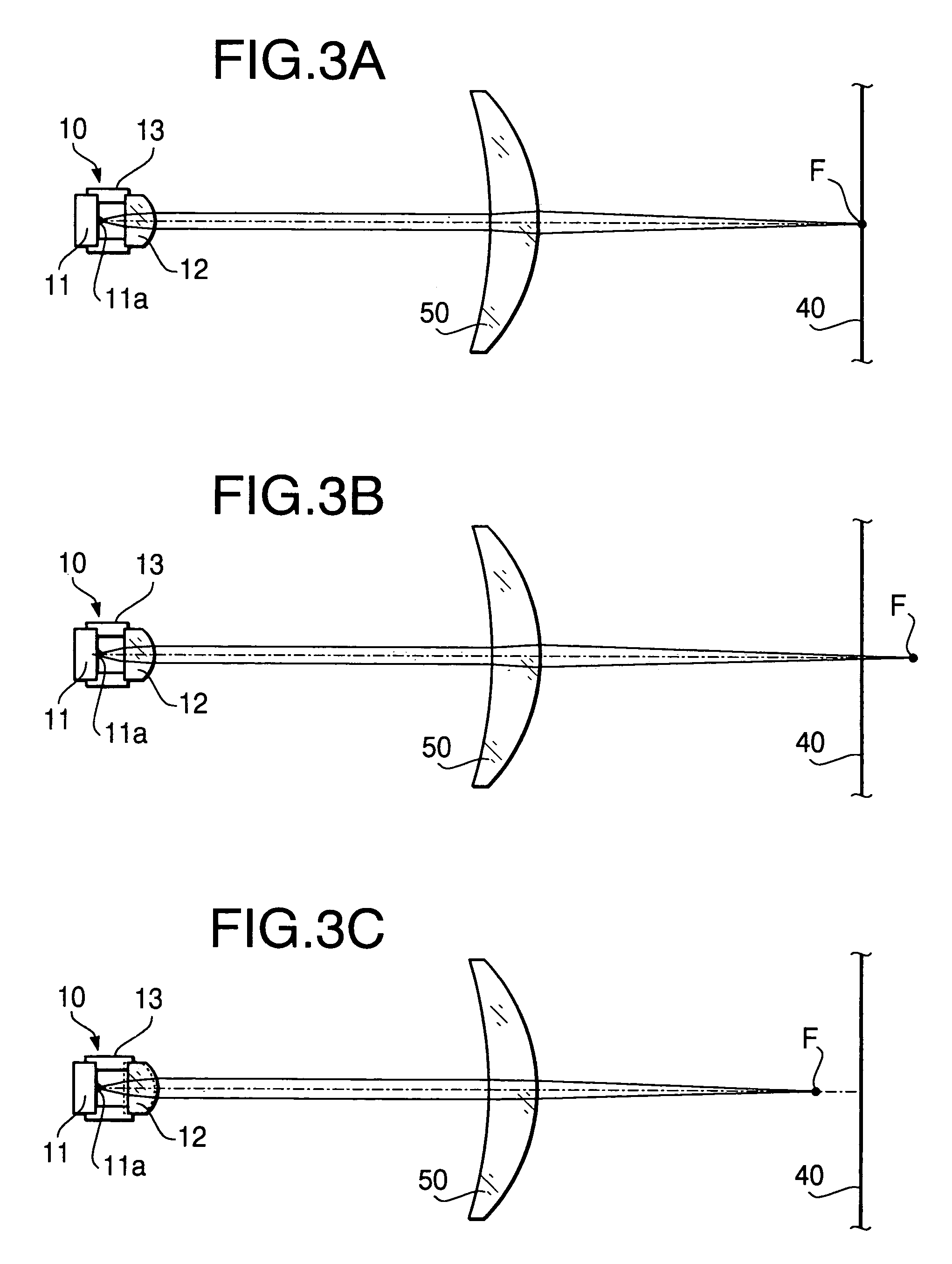
[0039]According to the above configuration, the deviation ΔS of the focusing point due to the change in refractive index of the scanning lens 50 and due to the linear expansion thereof when the temperature change ΔT of +10 degrees C. is +0.40 mm, while the deviation ΔV of the focusing point due to the linear expansion of the support member 13 is −0.36 mm. As a result, the overall deviation of the focusing point can be suppressed to +0.04 mm.
example 2
[0040]The collimating lens 12 according to Example 2 is configured as indicated in Table 2. The focal length fc of the collimating lens according to Example 2 is 12.0 mm.
[0041]
TABLE 2radius ofsurfacerefractivecurvaturedistanceindexR1 (light source side)∞10.001.82497R2 (polygonal mirror side)−9.900
[0042]In Example 2, the linear expansion coefficient α of the support member 13 is 4.50×10⁻⁵, the effective length L of the support member 13 is 6.5 mm, and the focal length f of the scanning lens 50 is 135.5 mm.
[0043]According to the above configuration, the deviation ΔS of the focusing point due to the change in refractive index of the scanning lens 50 and due to the linear expansion thereof when the temperature change ΔT of +10 degrees C. is +0.37 mm, while the deviation ΔV of the focusing point due to the linear expansion of the support member 13 is −0.37 mm. As a result, the overall deviation of the focusing point can be made to +0.00 mm.
example 3
[0044]The collimating lens 12 according to Example 3 is configured as indicated in Table 3. The focal length fc of the collimating lens according to Example 3 is 15.0 mm.
[0045]
TABLE 3radius of curvaturesurface distancerefractive indexR1 (light∞10.001.58252source side)R2 (polygonal−8.738mirror side)
[0046]In Example 3, the linear expansion coefficient α of the support member 13 is 4.50×10⁻⁵, the effective length L of the support member 13 is 8.7 mm, and the focal length f of the scanning lens 50 is 180.0 mm.
[0047]According to the above configuration, the deviation ΔS of the focusing point due to the change in refractive index of the scanning lens 50 and due to the linear expansion thereof when the temperature change ΔT of +10 degrees C. is +0.50 mm, while the deviation ΔV of the focusing point due to the linear expansion of the support member 13 is −0.56 mm. As a result, the overall deviation of the focusing point can be suppressed to −0.06 mm.
PUM
| Property | Measurement | Unit |
|---|---|---|
| focal length fc | aaaaa | aaaaa |
| focal length | aaaaa | aaaaa |
| focal length | aaaaa | aaaaa |
Abstract
Description
Claims
Application Information
 - R&D
- Intellectual Property
- Life Sciences
- Materials
- Tech Scout
- Unparalleled Data Quality
- Higher Quality Content
- 60% Fewer Hallucinations
Browse by: Latest US Patents, China's latest patents, Technical Efficacy Thesaurus, Application Domain, Technology Topic, Popular Technical Reports.
© 2025 PatSnap. All rights reserved.Legal|Privacy policy|Modern Slavery Act Transparency Statement|Sitemap|About US| Contact US: help@patsnap.com


