Heat treatment method and heat treatment device

a heat treatment device and heat treatment method technology, applied in the direction of muffle furnaces, instruments, furnaces, etc., can solve the problems of difficult to efficiently process objective wafers by thermal processes, low efficiency, and low efficiency of dummy workpieces, so as to reduce the number of dummy workpieces, improve the uniformity of inter-workpieces, and improve the effect of heat treatment efficiency

Inactive Publication Date: 2005-12-13
TOKYO ELECTRON LTD
View PDF8 Cites 11 Cited by
  • Summary
  • Abstract
  • Description
  • Claims
  • Application Information

AI Technical Summary

Benefits of technology

[0008]The present invention has been made in view of the foregoing circumstances and it is therefore an object of the present invention to provide a thermal processing apparatus and a thermal processing method capable of reducing the number of dummy workpieces that are used when a number of objective workpieces less than the workpiece holding capacity of a workpiece holder are held on the workpiece holder and subjected to a thermal process, and of stably processing the objective workpieces by a desired thermal process in satisfactory inter-workpiece uniformity and satisfactory in-surface uniformity.
[0019]According to the present invention, when workpieces smaller in number than the holding capacity of the workpiece holder are to be subjected to a thermal process, processing conditions are set for workpiece distribution patterns corresponding to the numbers of workpieces. Therefore, dummy workpieces necessary to realize a selected workpiece distribution pattern exactly are loaded together with the workpieces into the workpiece holder. Thus, the number of necessary dummy workpieces can be reduced, whereby the running cost can be reduced and the workpieces can be efficiently processed by the predetermined thermal process. Moreover, since the workpieces can be distributed exactly conforming to the selected distribution pattern, each of the workpieces can be processed basically in high in-surface uniformity, and the workpieces disposed at different positions can be processed in high inter-workpiece uniformity.
[0020]Since a workpiece distribution pattern in which workpieces to be subjected to a thermal process are distributed in the workpiece holder is selected on the basis of the number of the workpieces, and processing conditions for the selected workpiece distribution pattern are determined automatically, a pattern of distributing the workpieces in the workpiece holder, and the processing conditions can be very easily set.
[0022]Particularly, when the number of workpieces to be processed is smaller than the reference number for a workpiece distribution pattern corresponding to a batch size range having a maximum smaller than half the holding capacity of the workpiece holder, the workpieces are distributed in the workpiece holder uniformly with at least one vacant holding space secured between the adjacent workpieces. Therefore, processing conditions including temperature and concentrations of process gases are substantially the same for all the workpieces. Consequently, each of the workpieces can be processed in a high in-surface uniformity, and the workpieces disposed at different positions can be processed in high inter-workpiece uniformity.
[0036]The frequency of using the dummy workpieces can be reduced and time necessary for loading the workpiece holder with workpieces for each cycle of the thermal process by preparing workpiece distribution patterns respectively for different batch sizes. Throughput can be increased and load on operators can be decreased by automating a series of operations for workpiece distribution pattern selection, calculating the number of workpieces to be placed in spaces to be filled in a selected workpiece distribution pattern, and loading workpieces and, when necessary, dummy workpieces into the workpiece holder.
[0037]A workpiece distribution pattern that reduces the number of necessary dummy workpieces can be readily and quickly selected, and thereby the aforesaid effects can be enhanced.

Problems solved by technology

Therefore, wafer boats are often not fully loaded.
Thus, the dummy wafers increase the running cost and hence it is difficult to process objective wafers efficiently by a thermal process.

Method used


Image

  • Heat treatment method and heat treatment device
  • Heat treatment method and heat treatment device
  • Heat treatment method and heat treatment device

Examples


first embodiment

[0050

[0051]A vertical thermal processing apparatus in a first embodiment carries out a CVD process, i.e., a thermal process, to deposit a film on semiconductor wafers, i.e., workpieces.

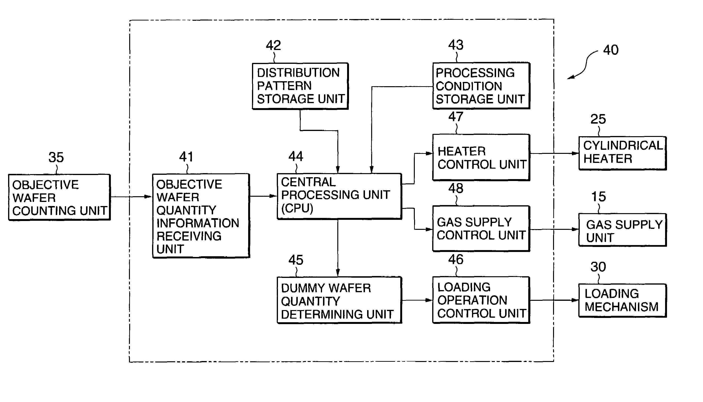
[0052]FIG. 1 is a schematic sectional view of a thermal processing apparatus in a first embodiment according to the present invention.

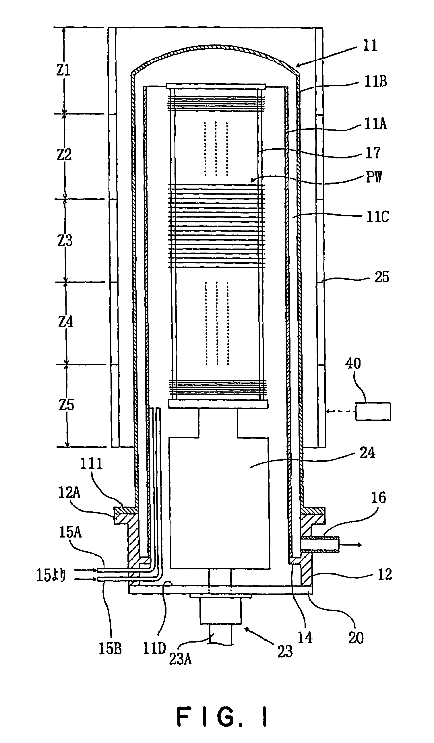
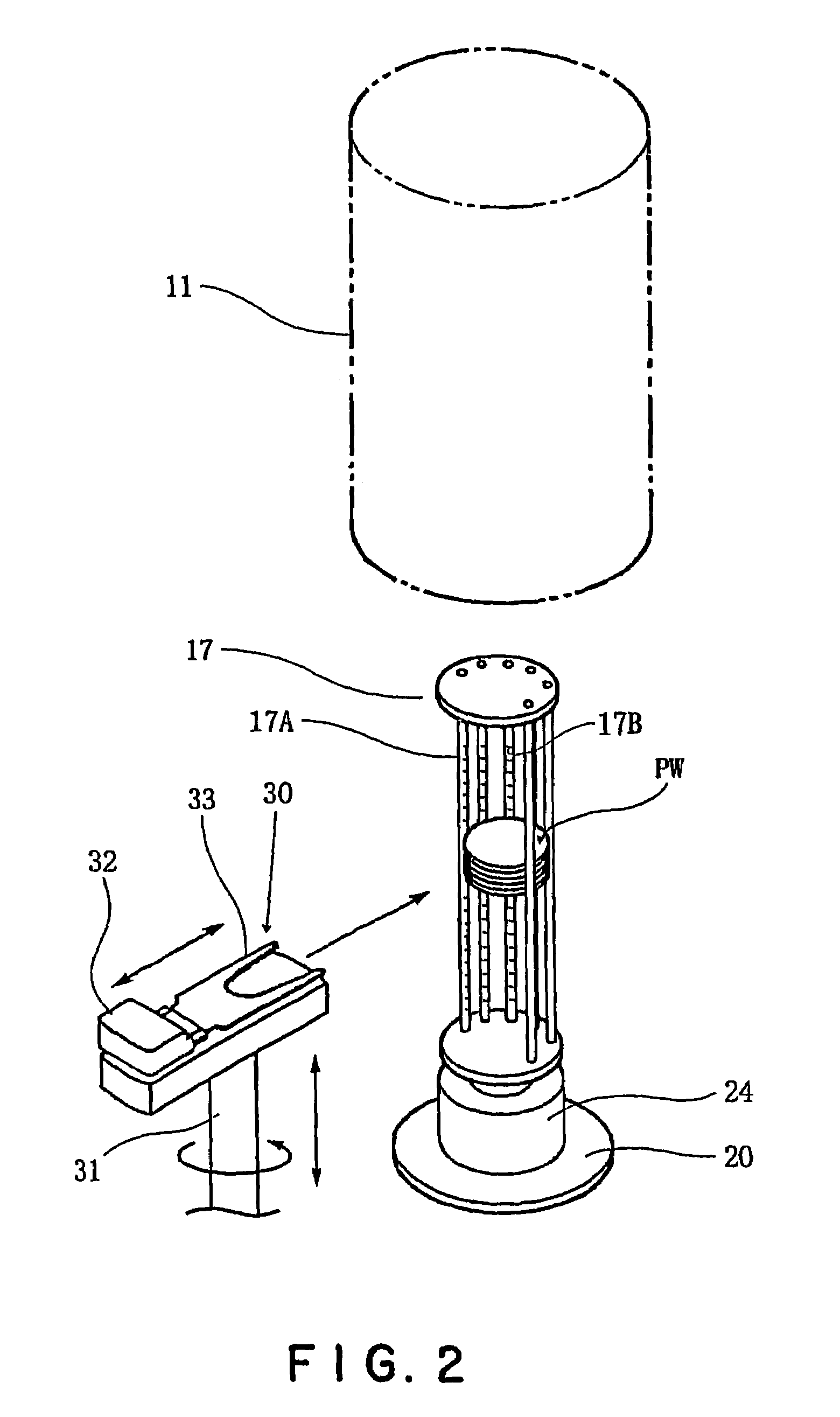
[0053]The vertical thermal processing apparatus has a double-wall reaction tube (processing tube) 11 including a straight inner tube 11A set in an upright position and having an open upper end, and an outer tube 11B disposed coaxially with the inner tube 11A so as to surround the inner tube 11A and having a closed upper end. The inner tube 11A and the outer tube 11B define an annular space 11C. A loading zone extends under the reaction tube 11. Objective semiconductor wafers PW are loaded into a wafer boat 17 in the loading zone.

[0054]The inner tube 11A and the outer tube 11B are formed of a heat-resistant, corrosion resistant material, such as quartz glass of a high pu...

experiment 1

[0104

[0105]Twenty objective wafers (PW) were loaded into a wafer boat (17) having a holding capacity of 100 wafers in the reference distribution pattern L25 shown in FIG. 3. Five dummy wafers were placed in the vacant holding parts in the objective wafer distribution region R. The thus loaded wafer boat (17) was carried into a reaction tube (11) to subject the objective wafers (PW) to a film deposition process for depositing a silicon nitride film (SiN film) in a desired thickness of 150 nm. The processing conditions for the reference distribution pattern L25 included heating the objective wafers (PW) at a desired temperature (processing temperature) of 760° C. The thickness uniformity of the SiN film formed on each objective wafers (PW), i.e., the in-surface uniformity, was ±1.0%. The inter-wafer thickness uniformity between the semiconductor wafer held in the 17th holding part from the bottom, i.e., the lowermost monitor wafer MW in FIG. 3, and the semiconductor wafer held in the ...

second embodiment

[0109

[0110]A vertical thermal processing apparatus in a second embodiment will be described as applied to carrying out a thermal process. FIGS. 5 and 6 show the vertical thermal processing apparatus in the second embodiment. Shown in FIG. 5 are a casing 120, i.e., housing, a receiving / delivering unit 121, a carrier carrying mechanism 122, a carrier storage unit 123, and a transfer stage 124. A carrier C containing semiconductor wafers (hereinafter, referred to simply as “wafer”) W, i.e., workpieces, not shown in FIG. 5, delivered to the receiving / delivering unit 121 is carried by the carrier carrying mechanism 122 to the carrier storage unit 123 for temporary storage. The carrier C is carried from the carrier storage unit 123 to the transfer stage 124. A wafer carrying mechanism 103 is installed in a wafer loading chamber 125. The wafer carrying mechanism 103 takes out the wafers W from the carrier C placed on the transfer stage 124, and transfers the wafers W to a wafer boat 127, i...


PUM

PropertyMeasurementUnit
thicknessaaaaaaaaaa
temperatureaaaaaaaaaa
thicknessaaaaaaaaaa

Abstract

A thermal processing method selects a batch size range including the number of workpieces to be processed from a plurality of batch size ranges including batch size ranges in which reference numbers smaller than the holding capacity of a workpiece holder are maximums. The workpieces are distributed in the workpiece holder on the basis of the workpiece distribution pattern determined corresponding to the specified batch size range. Processing conditions of the thermal process are determined according to the workpiece distribution pattern. A thermal processing apparatus comprises a controller capable of carrying out the thermal processing method.

Description

TECHNICAL FIELD[0001]The present invention relates to a thermal processing method and a thermal processing apparatus. More specifically, the present invention relates to a batch thermal processing method of hot-processing a plurality of workpieces in a batch, and a batch thermal processing apparatus for carrying out the same.BACKGROUND ART[0002]A semiconductor device manufacturing process uses various thermal processing systems for processing workpieces, such as semiconductor wafers, by thermal processes including an oxidation process, a diffusion process and a film formation process. For example, a known batch vertical thermal processing apparatus is capable of processing a plurality of workpieces simultaneously by a thermal process.[0003]This known vertical thermal processing apparatus processes a plurality of semiconductor wafers by a desired thermal process by placing a wafer boat, i.e., a workpiece holder, holding the semiconductor wafers in a horizontal position at predetermin...

Claims


Application Information

Patent Timeline
Patent Type & Authority Patents(United States)
IPC IPC(8): F27D19/00H01L21/00
CPCF27D19/00H01L21/67098H01L21/67253H01L21/67109Y10T29/41H01L21/324
Inventor SAKAMOTO, KOICHITAKENAGA, YUICHIYOKOTA, TAKASHIKAWAMURA, KAZUHIRO
Owner TOKYO ELECTRON LTD
Why Eureka
Try Eureka