Flexible interlocking-column packaging assembly

a flexible, interlocking-column technology, applied in the direction of packaging foodstuffs, sustainable manufacturing/processing, packaged goods, etc., can solve the problems of not being able to be reused economically, affecting the use effect, and consuming too much material, etc., to achieve the effect of convenient us

Inactive Publication Date: 2005-12-20
LENOVO PC INT
View PDF10 Cites 17 Cited by
  • Summary
  • Abstract
  • Description
  • Claims
  • Application Information

AI Technical Summary

Benefits of technology

[0007]Thus, a packaging assembly comprising a standard molded cushion solution that can accommodate variations in dimensions of predetermined products, including weight, while providing protection to an equipment component (or other fragile or breakable item) enclosed therein, ease in use during pre-packing and packing of an equipment component for transport, shock protection during transport, and is economically suited for its end use, is desired.

Problems solved by technology

Unfortunately, each of these methods is only satisfactory in protecting the equipment during transport, and each have varied costs associated therewith.
However, each has a set of known design and / or use limitations.
For foam materials, though cushioning and protection are generally good characteristics, they use too much material and cannot be recycled economically.
Pulp-based materials however, though abundant and relatively inexpensive, have proven to be inadequate for the routine or repeated transport of sensitive components and electrical devices.
Additionally, it is quite common in the industry, due in part to the lesser costs of using pulp-based materials, to redesign a packaging container for every unique type of product to be transported or shipped; this effort of redesigning or customizing to accommodate even variations within product lines is often time-consuming and costly in labor.
Additionally, where there is addition packaging assemblies for varied products in the same product families, there is also usually associated with those packaging assemblies, additional inventory, part numbers, material costs, tooling costs and efforts related to tracking.

Method used


Image

  • Flexible interlocking-column packaging assembly
  • Flexible interlocking-column packaging assembly
  • Flexible interlocking-column packaging assembly

Examples


Embodiment Construction

[0017]The use of figure reference labels in the claims is intended to identify one or more possible embodiments of the claimed subject matter in order to facilitate the interpretation of the claims. Such labeling is not to be construed as necessarily limiting the scope of those claims to the embodiments shown in the corresponding figures. The preferred embodiments of the present invention and its advantages are best understood by referring to the drawings, like numerals being used for like and corresponding parts of the various drawings. Reference herein to “one embodiment” or “an embodiment” means that a particular feature, structure, or characteristic described in connection with the embodiment can be included in at least one embodiment of the invention, but not necessarily in all. The appearances of the phrase “in one embodiment” in various places in the specification, sequentially or otherwise, does not necessarily indicate that each phrase refers to or is used in reference to t...


PUM

PropertyMeasurementUnit
compositionaaaaaaaaaa
shapeaaaaaaaaaa
distanceaaaaaaaaaa

Abstract

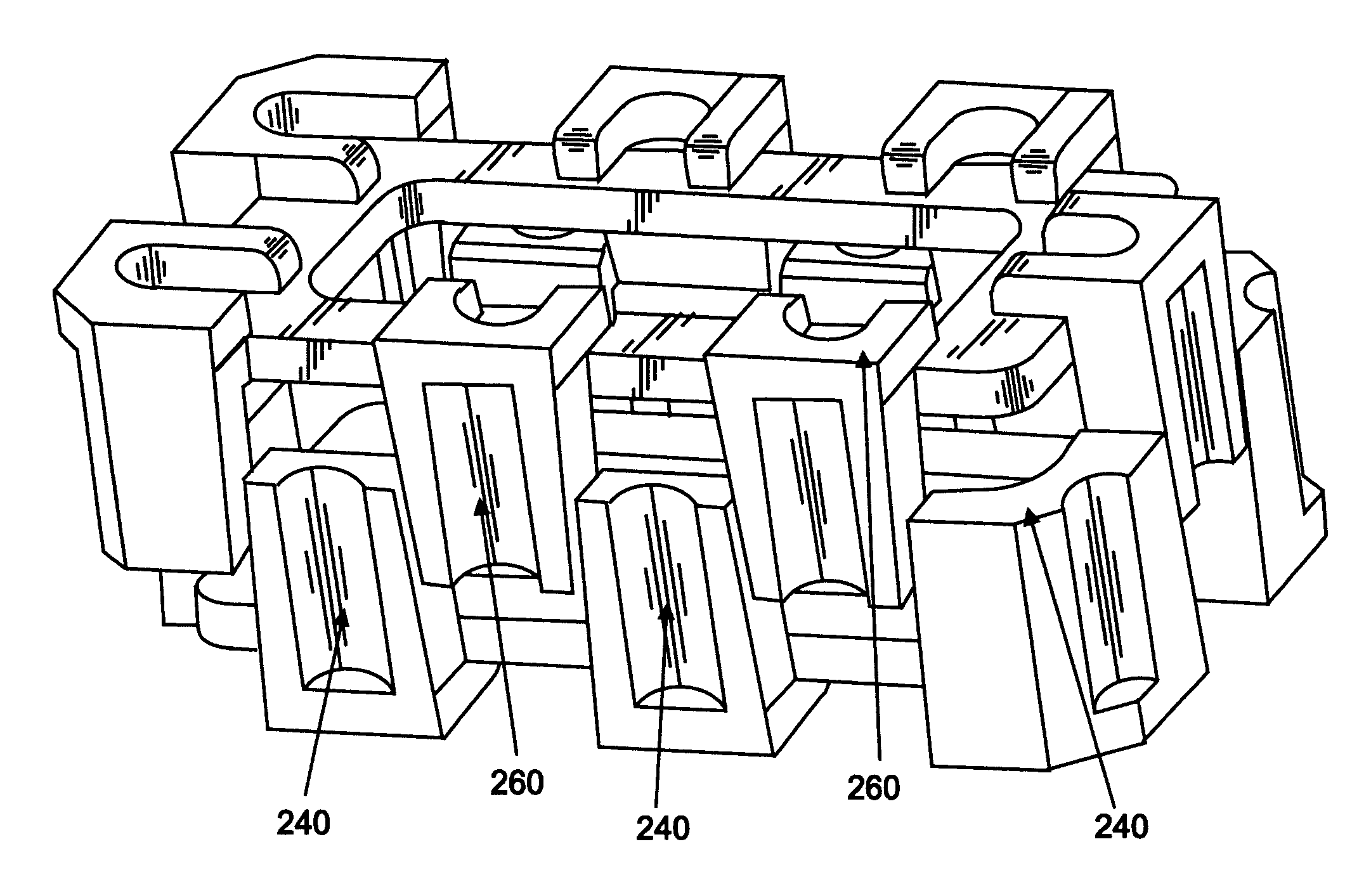
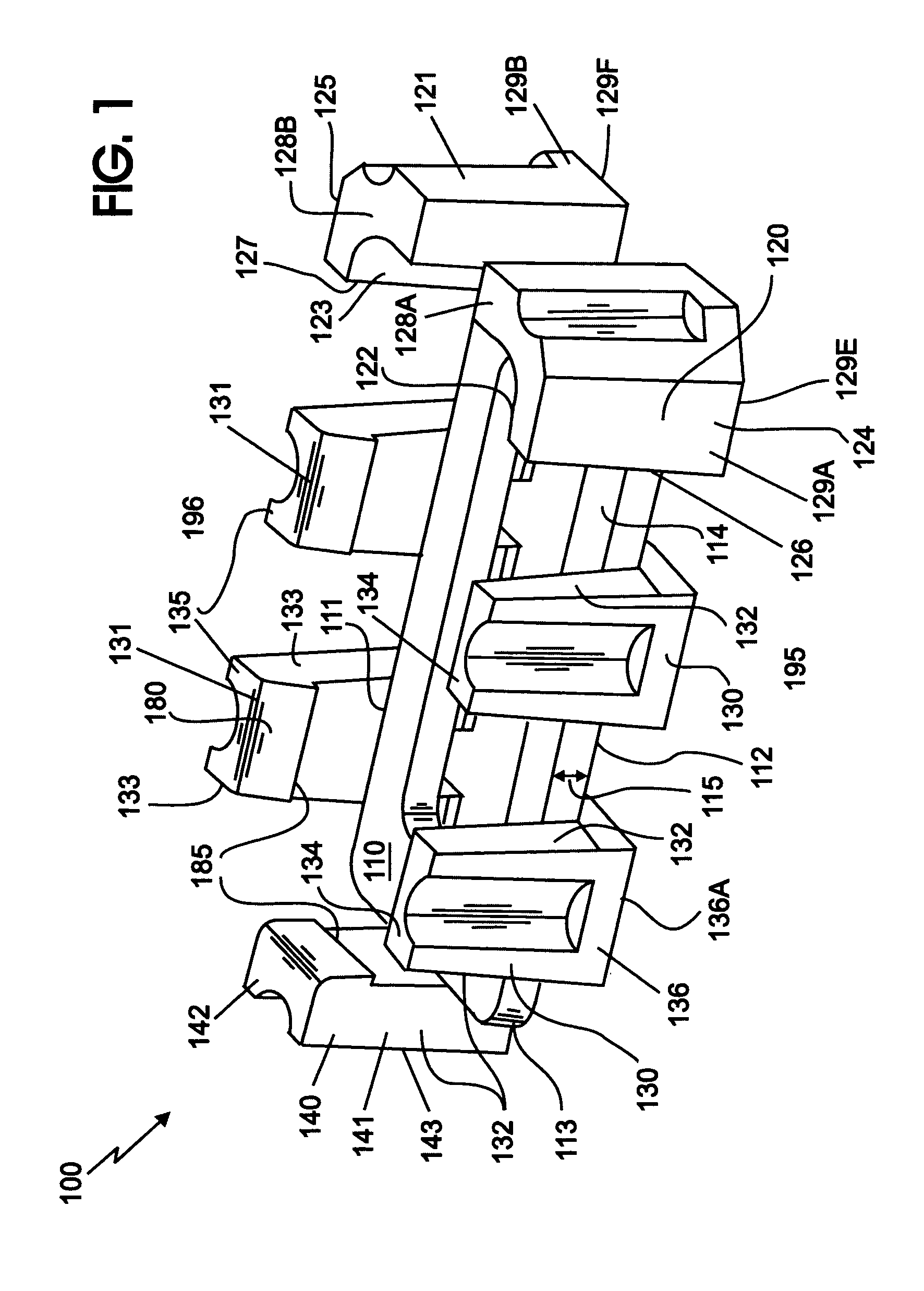
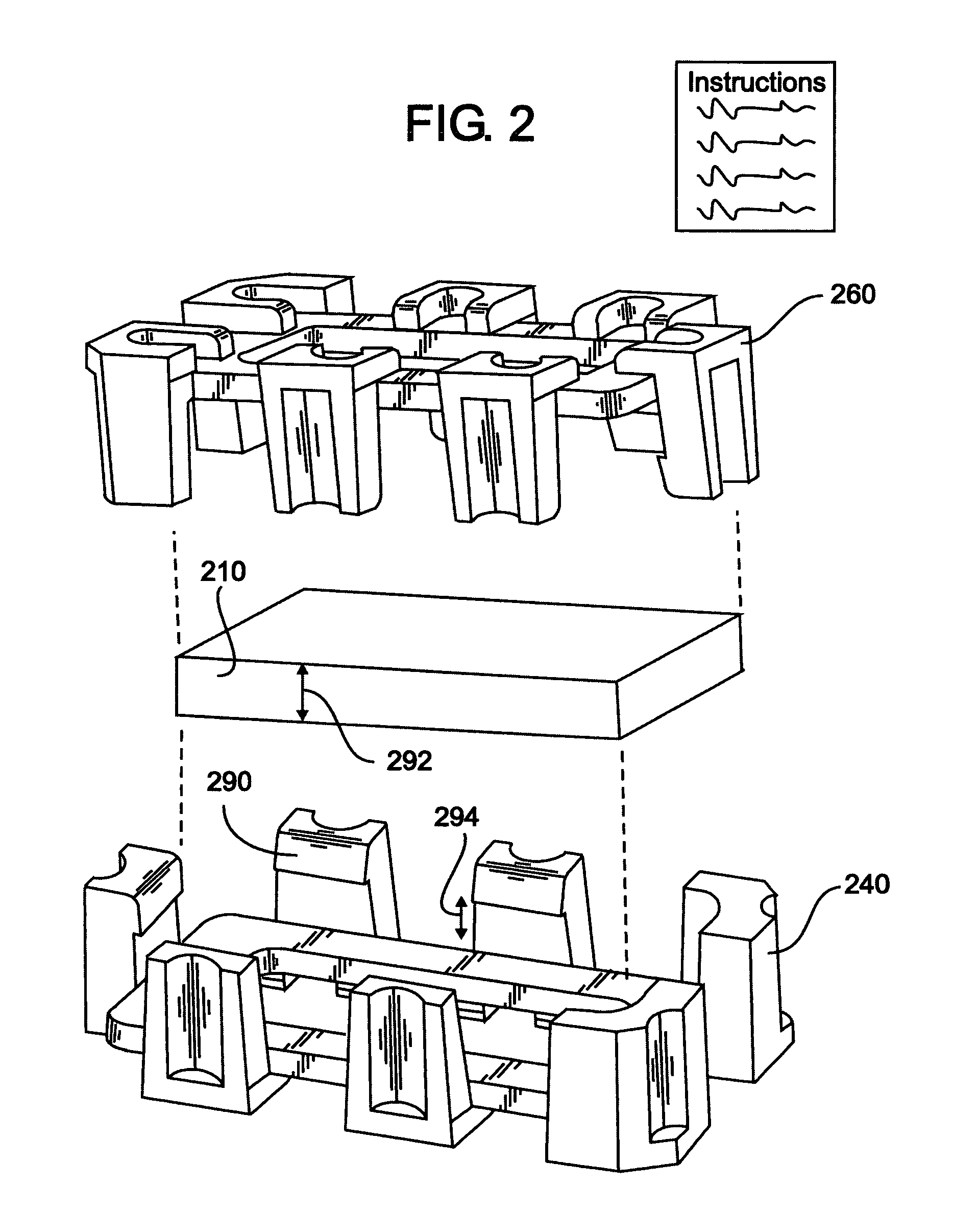
A packaging assembly comprising a standard molded cushion solution that can accommodate variations in dimensions of predetermined products, including weight, while providing protection to an equipment component (or other fragile or breakable item) enclosed therein, ease in use during pre-packing and packing of an equipment component for transport, shock protection during transport, and is economically suited for its end use, is provided for. The present invention is a molded, cushion having interlocking columns which adjust the contacting areas of the cushion in relation to the product height and / or weight differences. The present invention is advantageously designed using specific geometries and interlocking columns which, contrary to traditional designs, benefit from the stressing and flexing characteristics of paper fiber.

Description

BACKGROUND OF THE INVENTION[0001]1. Field of the Invention[0002]The present invention relates generally to the protective packaging systems and apparatuses therein, and more particularly to a creating a molded pulp cushion and tray packaging apparatus having a universal top and a universal bottom cushion for protectively accommodating fragile items often associated with electronic equipment, especially during post-manufacturing and transport, without the need for additional packing materials.[0003]2. Description of Related Art[0004]It is known that one way to protect electronic equipment (e.g., computer displays, electronic component boards, thin lead electronics, and the like) is to wrap or surround the equipment in packing foam, bubble wrap or polyurethane pellets before or concurrent with setting such equipment into a shipping container for transport. Other methods includes shipping these electronic components via parallelpiped cardboard containers, specially-molded containers or...

Claims


Application Information

Patent Timeline
Patent Type & Authority Patents(United States)
IPC IPC(8): B65D21/08B65D81/113B65D85/30B65D85/38B65D85/68
CPCB65D21/086B65D81/113B65D85/30B65D85/38B65D2585/6837Y02W90/10
Inventor LIVERMAN, IVAN NEILMARESH, MARK EDMUNDMILLER, JEFFREY JAYSTEGNER, ERIC ALLENSTEGNER, ROBERT WILLIAMTURNER, CHRISTOPHER MICHAEL
Owner LENOVO PC INT
Why Eureka
Try Eureka