System and method for single-sided magnetic resonance imaging

a single-sided magnetic resonance and imaging system technology, applied in the field of magnetic resonance imaging, can solve the problems of poor spatial resolution, poor reception signal, and device described above that does not allow effective depth resolution, and achieve the effect of uniform magnetic field strength

Inactive Publication Date: 2005-12-20
QUANTUM MAGNETICS
View PDF6 Cites 33 Cited by
  • Summary
  • Abstract
  • Description
  • Claims
  • Application Information

AI Technical Summary

Benefits of technology

[0010]Embodiments of the present invention provide a portable MRI device and method to measure material properties with spatial resolution in a non-invasive manner. The spatial resolution may be a depth profile or lateral (parallel to the sensor surface) resolution, or a combination of them, to render information in one, two, or three dimensions. Measurements may be made directly from the surface of the material under test. Embodiments of the invention include a dedicated array of permanent magnets to provide flat surfaces of substantially uniform magnetic field strength above and parallel to a surface of the array. The field is virtually uniform within horizontal degrees of freedom and decreases monotonically in a direction away from the surface. This direction is vertical or outward from the surface of the array within the framework of the present description, but may comprise any orientation when an instrument according to the present invention is utilized.

Problems solved by technology

If the frequency is shifted without proper retuning, the received signal degrades rapidly.
The devices described above do not allow for effective depth resolution, due to their inherent magnetic field distribution.
A frequency shift in the presence of non-flat surfaces of constant magnetic field is associated with a displacement of the sensitive volume with poor spatial resolution.

Method used


Image

  • System and method for single-sided magnetic resonance imaging
  • System and method for single-sided magnetic resonance imaging
  • System and method for single-sided magnetic resonance imaging

Examples


Embodiment Construction

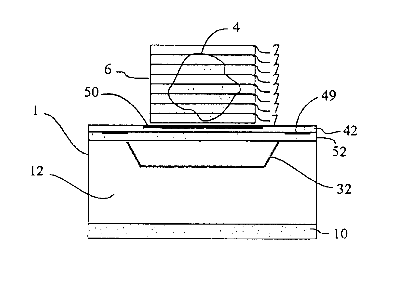
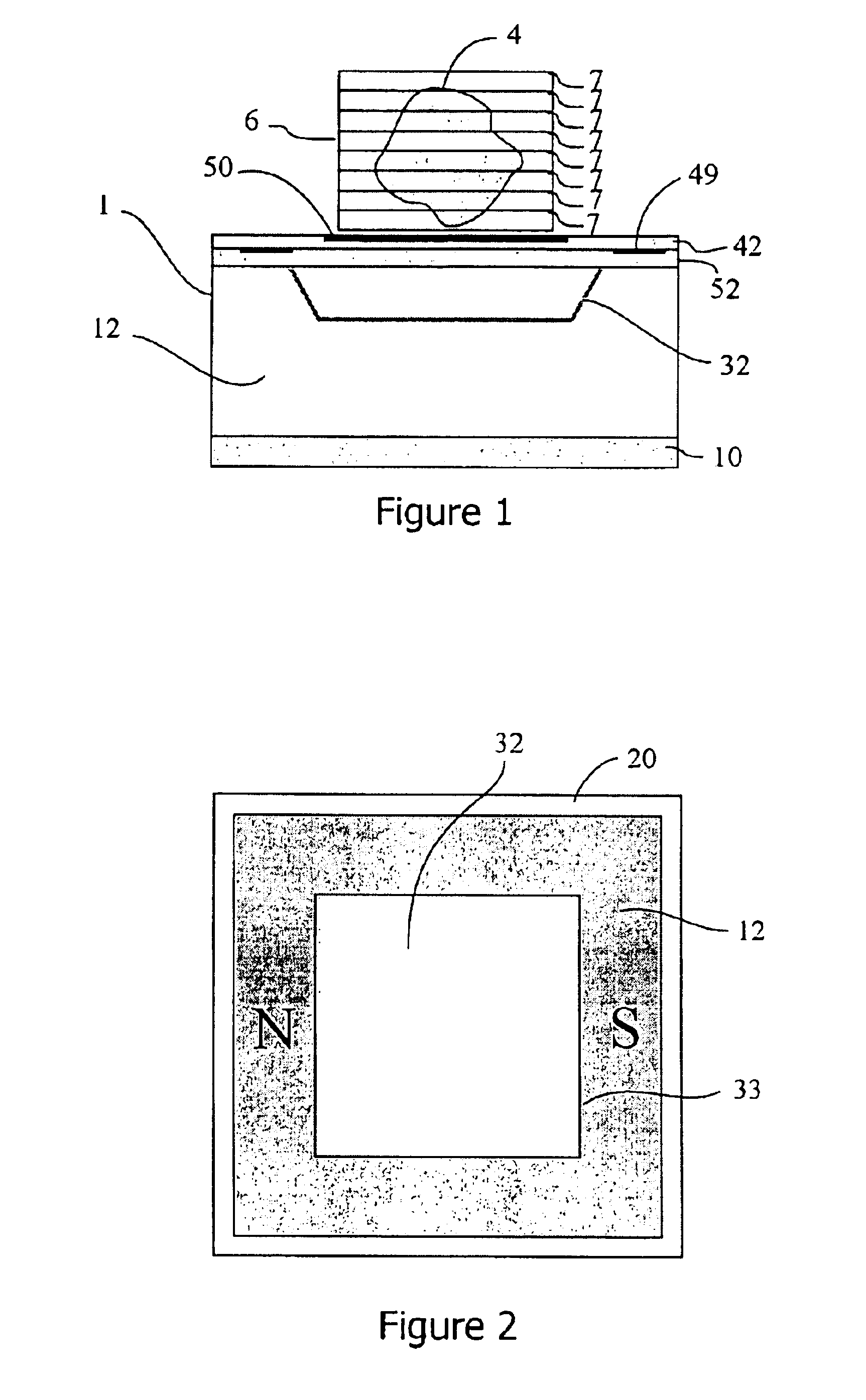
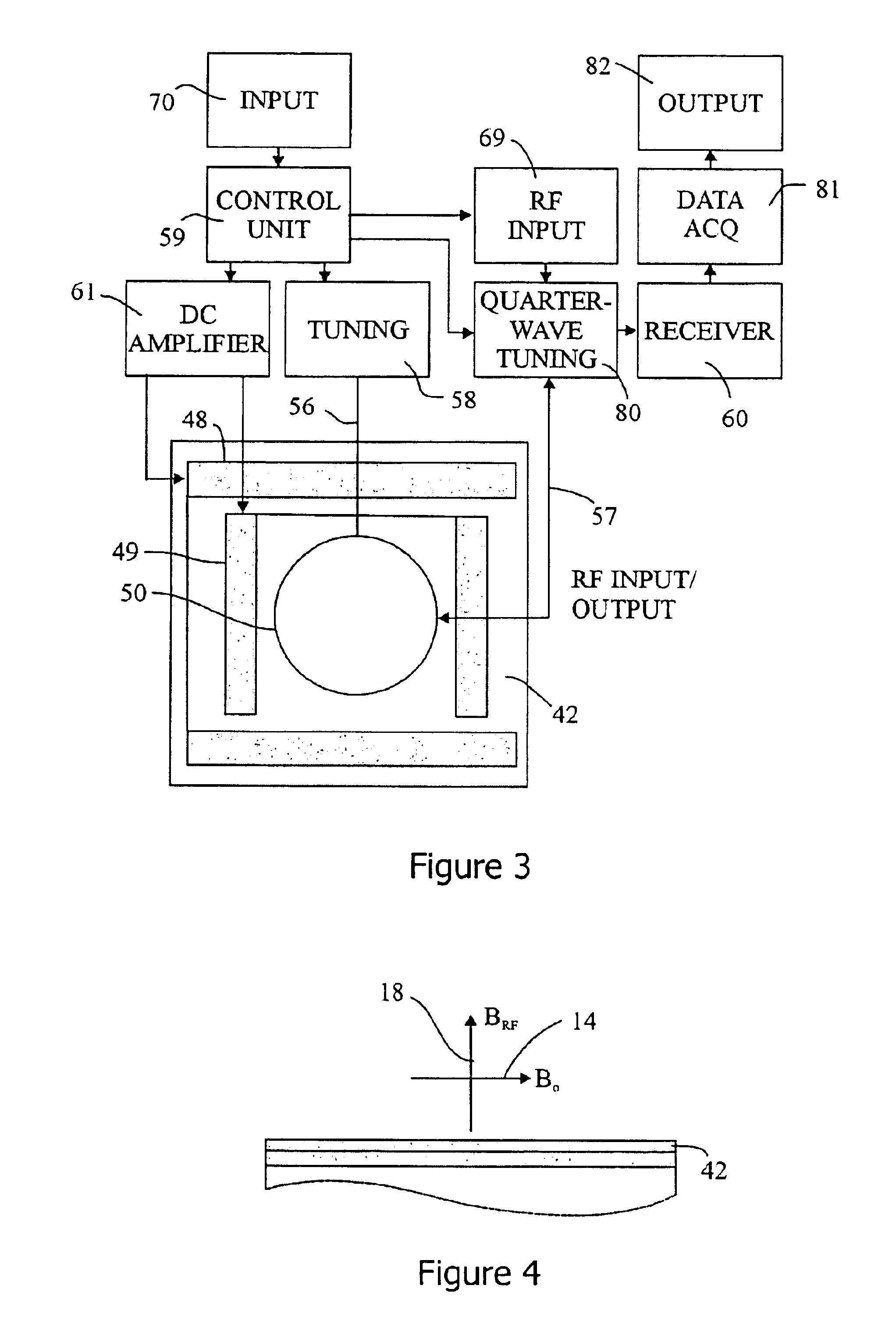
[0022]With reference now to the drawing, and more particularly to FIG. 1, single-sided MRI probe head 1 is illustrated. The MRI apparatus provides for analysis of sample 4 placed in a sensitive volume 6 on one side thereof. In the embodiment of FIG. 1, the sensitive volume is above the MRI probe head. It should be understood that the deployment of the present invention does not require any one particular spatial orientation. Sensitive volume 6 could indeed be below or beside the MRI apparatus. Relative orientations of the components of MRI probe head 1 and sample 4 to be analyzed are described below. The MRI probe head includes magnet assembly 12 and RF coil unit 50. For in-plane imaging, magnetic field gradient coils 48 and 49 (see FIG. 3) are used. In conjunction with FIG. 1, FIG. 2 is a plan view of magnet assembly 12, and FIG. 3 is a plan view of the RF coil 50 and gradient coils 48 and 49, together with a block diagram of the RF unit.

[0023]Magnet assembly 12 preferably comprise...


PUM


Abstract

A magnetic resonance imaging apparatus and method having a magnet assembly, which provides substantially flat surfaces of constant magnetic field outside the assembly and a set of magnetic field gradients. One-, two-, and three-dimensional images are rendered. The static magnetic field is virtually uniform within horizontal degrees of freedom and decreases monotonically in a direction away from the surface. An RF probe, for example, a coil, located adjacent the surface, produces a field substantially perpendicular to the static magnetic field. A magnetic field gradient is set to horizontally scan a given level within the sensitive volume. Received magnetic resonance signals are detected by the coil for a depth corresponding to the excitation frequency. As the tuning and excitation frequency is switched to lower values, signals are generated for layers progressively farther from the surface. The RF probe is automatically tuned. Depth profiles are rendered by concatenating the signals collected at various frequencies. Horizontal resolution is attained by the use of controlled magnetic field gradients.

Description

BACKGROUND OF THE INVENTION[0001]1. Field of the Invention[0002]Embodiments of the present invention relate generally to magnetic resonance imaging, and more particularly to a method and apparatus for producing one-, two- and three-dimensional imaging employing a single-sided magnet and a dedicated radio-frequency coil.[0003]2. Discussion of Related Art[0004]In conventional magnetic resonance imaging (MRI), a scanned sample, which may be a patient or a sample of inanimate material, is placed in a substantially uniform, temporally constant main magnetic field within a defined volume. For purposes of the present description, the volume within which meaningful results will be produced is referred to as the sensitive volume. The magnetic field causes nuclear spins within the sample to effectively line up parallel to the field direction. This orientation is permuted by exciting those nuclei with one or many radio-frequency (RF) pulses. As these excited nuclei realign to the external magn...

Claims


Application Information

Patent Timeline
Patent Type & Authority Patents(United States)
IPC IPC(8): G01R33/38G01R33/48
CPCG01R33/3806G01R33/48
Inventor PRADO, PABLO J.
Owner QUANTUM MAGNETICS
Why Eureka
Try Eureka