Secondary coil circuit for use with a multi-section protected superconductive magnet coil circuit

a secondary coil circuit and superconductive magnet technology, applied in the field of superconducting or superconductive magnets, can solve the problems of constant circulating of electric current, burnt and permanently damaged parts of the mri system, and high cost of permanent damag

Active Publication Date: 2005-12-20
GENERAL ELECTRIC CO
View PDF15 Cites 61 Cited by
  • Summary
  • Abstract
  • Description
  • Claims
  • Application Information

AI Technical Summary

Benefits of technology

[0019]In one preferred embodiment, the number, the physical characteristics, and the positions of the secondary coils are all selected to cooperatively minimize mutual induction between each of the individual sections of the multi-section protected superconductive magnet coil circuit and the secondary coil circuit during a quench event in the multi-section protected superconductive magnet coil circuit. In this way, electric current in the secondary coil circuit is prevented from being induced to rise to a predetermined unstable current level. In such an embodiment, the predetermined unstable current level may, for example, be substantially commensurate with the characteristic critical current level for the wire of the secondary coils.
[0021]In still another preferred embodiment, the secondary coil circuit further includes at least one quench-inducing resistive heater thermally coupled to at least one of the secondary coils and electrically connected in parallel with at least one of the superconductive magnet coils situated in the multi-section protected superconductive magnet coil circuit. Coupled and connected as such, each quench-inducing resistive heater is thereby positioned and designed for voltage-activation by the multi-section protected superconductive magnet coil circuit to preemptively initiate quenching in the secondary coil circuit. In this way, electric current in the secondary coil circuit is prevented from being induced to rise to a predetermined unstable current level during a quench event in the multi-section protected superconductive magnet coil circuit.

Problems solved by technology

In emergency situations, it may be necessary to intentionally shut down an MRI system in a very short timeframe.
In light of such, therefore, if the electric current is ramped down and quenched too quickly or abruptly, large uncontrolled amounts of heat may suddenly be generated and emitted from the loop which could burn and permanently damage parts of the MRI system, including one or more sections of the loop itself and its magnet coils, or even other surrounding hardware.
Any such permanent damage can be costly.
Sometimes, electric current persistently circulating through the superconductive magnet coil circuit may suddenly be quenched by accident due to an unanticipated thermal disturbance which causes one or more sections of the persistent loop to become resistive.
For example, in one possible scenario, mechanical stress and frictional movement of one or more superconductive magnet coils during operation may cause localized frictional heating which, if significant enough, may cause rapid and uncontrolled quenching of the electric current in the circuit.
In another possible scenario, if liquid cryogens within the cryostat are not properly replenished to maintain the overall magnet coil circuit at a sufficiently cold temperature below its characteristic critical temperature (TCRIT), one or more localized resistive “hot spots” may develop in the persistent loop which may cause rapid and uncontrolled quenching of the electric current in the magnet coil circuit.
In either such scenario and in many possible others, such rapid and uncontrolled quenching is likely to cause the release and emission of significant amounts of thermal energy (for example, up to 80 mega-joules (MJ)) in the form of heat.
As a consequence of such thermal energy being “dumped” in this manner, parts of the MRI system may be burned and permanently damaged, including one or more sections of the loop itself and its magnet coils, and even surrounding hardware.
Hence, as with intentional quenching, accidental quenching can be damaging and costly as well.
With, however, the push in recent years for MRI systems to accommodate higher electric currents and voltages as well as generate stronger magnetic fields to facilitate improved scanning, such conventional magnet coil circuits are now somewhat more prone to suffer the deleterious effects of excessively high voltage levels between adjacent layers of coil windings and / or localized heat damage, especially if electric current in a circuit is quenched in a somewhat uncontrolled manner within only one or a few particular sections of the circuit.
In addition, as the electric current is dissipated via the coil, the strong magnetic field current-generated in that same coil will collapse, thereby dumping energy in the form of heat onto that very same coil.
As a result of such a highly localized release and dumping of energy, a burning “hot spot” may develop and cause permanent damage to the coil before all of the energy in the circuit has been released and dumped.
As a result, the shim coil circuit may inadvertently be permanently damaged.
With, however, the above-described recent advent of a multi-section protected superconductive magnet coil circuit wherein magnet coils are situated and protected within multiple looped sections of the circuit, addressing a magnet coil circuit as a whole for shim circuit design purposes is generally no longer practical or appropriate.
Thus, for any such given multi-section protected superconductive magnet coil circuit, it is generally no longer appropriate to simply address the magnet coil circuit as a whole for shim circuit design and damage protection purposes, for the behavior of such a magnet coil circuit is quite multi-faceted during a quench event.

Method used


Image

  • Secondary coil circuit for use with a multi-section protected superconductive magnet coil circuit
  • Secondary coil circuit for use with a multi-section protected superconductive magnet coil circuit
  • Secondary coil circuit for use with a multi-section protected superconductive magnet coil circuit

Examples


Embodiment Construction

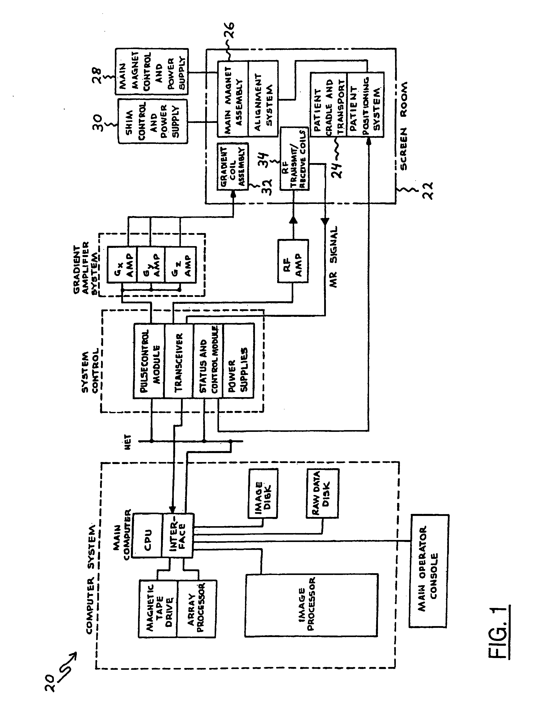
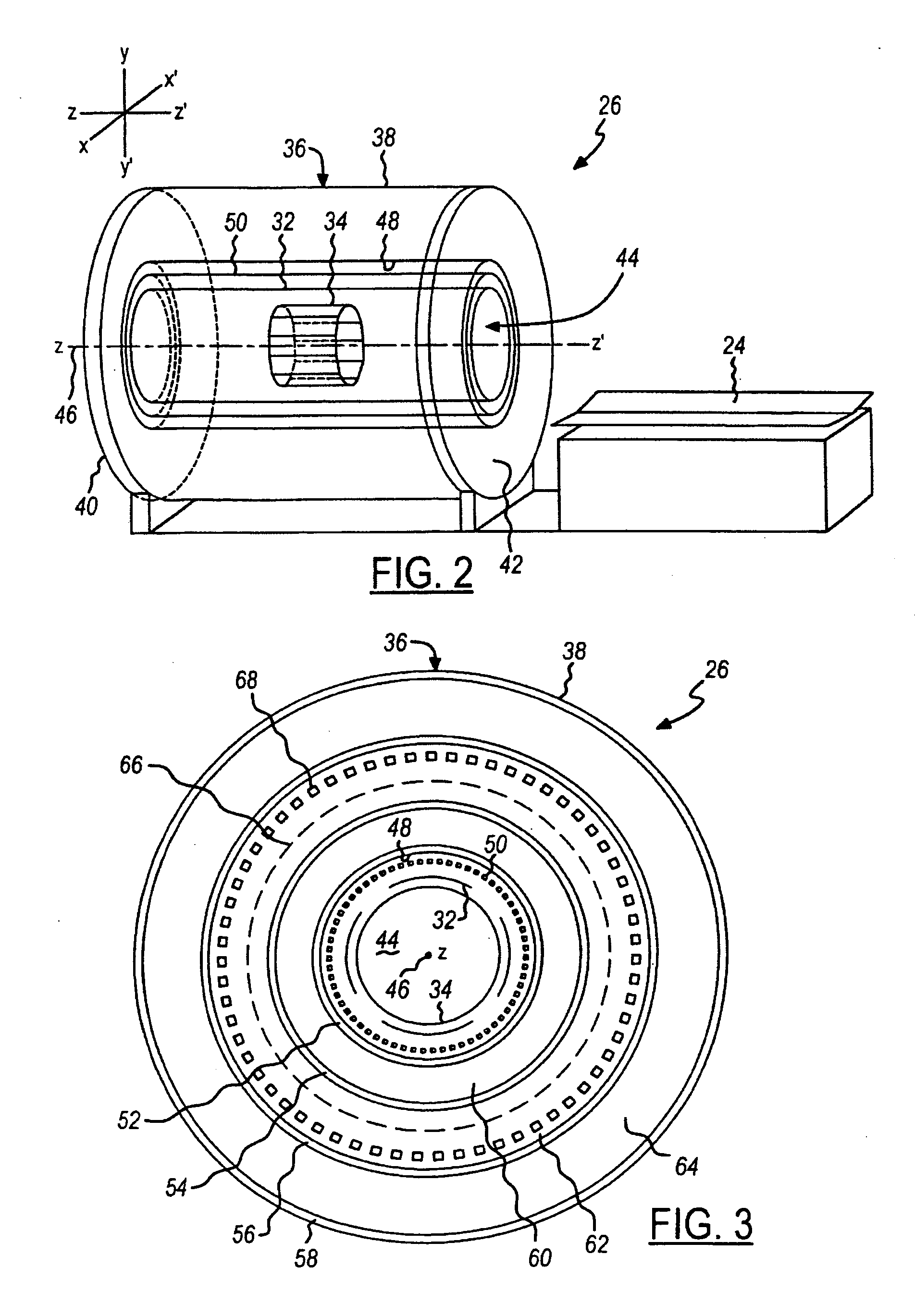
[0041]As an example, FIG. 1 shows a block diagram of a magnetic resonance imaging (MRI) system 20. Prior to operating the system 20, a patient is generally ushered into a shielded screen room 22. Once in the screen room 22, the patient is then situated in a supine position upon an electromechanical cradle-and-transport apparatus 24. After the patient is properly situated, the cradle-and-transport apparatus 24 is activated so as to move and thereby introduce the patient into an imaging bore defined within a main magnet assembly 26. Once in the main magnet assembly 26, the position of the patient is carefully aligned so as to focus in on an anatomic region of interest (ROI) within the patient's body. After being aligned, the patient is left immobilized within the main magnet assembly 26 in preparation for the system 20 to scan the patient.

[0042]When the MRI system 20 commences a scan operation, the designated region of interest (ROI) within the patient's body is immersed in a magnetic...


PUM

PropertyMeasurementUnit
critical temperatureaaaaaaaaaa
currentaaaaaaaaaa

Abstract

A secondary coil circuit for use with a multi-section protected superconductive magnet coil circuit is disclosed herein. The secondary coil circuit includes two circuit nodes, a ramping switch electrically connected between the two circuit nodes, and a number of secondary coils electrically connected between the two circuit nodes. The secondary coils are made of wire having substantially superconductive capability when cooled below a characteristic critical temperature level and conducting electric current below a characteristic critical current level. The secondary coils are sized and positioned relative to the superconductive magnet coils situated in the individual sections of the multi-section protected superconductive magnet coil circuit so as to functionally cooperate with the multi-section protected superconductive magnet coil circuit in producing and maintaining a magnetic field that is substantially homogeneous. In one embodiment, the secondary coil circuit is inductively decoupled from each individual section of the multi-section protected superconductive magnet coil circuit.

Description

FIELD OF THE INVENTION[0001]The present invention generally relates to superconducting or superconductive magnets. The present invention more particularly relates to primary superconductive magnet coil circuits and complementary secondary coil circuits that cooperatively produce magnetic fields suitable for use in, for example, nuclear magnetic resonance (NMR) spectroscopy systems, mass spectrometer systems, magnetic resonance imaging (MRI) systems, and the like.BACKGROUND OF THE INVENTION[0002]Magnetic resonance imaging (MRI) systems, for example, are frequently used in hospital and other medical facilities to scan and obtain images of biological tissues within a patient. By obtaining such images, a doctor or other medical professional can indirectly observe and carefully examine an anatomic region of interest (ROI) within a patient. Upon conducting such an examination, the doctor may then accurately diagnose a patient's malady and prescribe an appropriate treatment.[0003]To succes...

Claims


Application Information

Patent Timeline
Patent Type & Authority Patents(United States)
IPC IPC(8): H02H9/00H02H9/02
CPCG01R33/288G01R33/3806G01R33/3815G01R33/3875G01R33/421
Inventor HOLLIS, TIMOTHY JAMESFEENAN, PETER J.
Owner GENERAL ELECTRIC CO
Why Eureka
Try Eureka