Microstrip antenna for RF receiver

a microstrip antenna and receiver technology, applied in the field of antennas, can solve the problems of increasing the cost of components, weight, and suffering from the tendency to fail, and printing antennas, on the other hand, have space-consuming configurations, and achieve the effect of improving performance characteristics

Inactive Publication Date: 2005-12-20
OMRON AUTOMOTIVE ELECTRONICS CO LTD
View PDF26 Cites 58 Cited by
  • Summary
  • Abstract
  • Description
  • Claims
  • Application Information

AI Technical Summary

Benefits of technology

[0003]The present invention is directed to a spiral shape antenna which can be printed directly on a PCB and which exhibits improved performance characteristics with respect to the conventional printed type antenna such as the above-mentioned spiral configuration.
[0013]Another aspect of the invention resides in a method of improving reception of a rectangular spiral antenna which is disposed on a circuit board and adapted to receive a signal from a remote transmitter, comprising providing sharp corners at the intersections which interconnect straight portions of the rectangular spiral antenna. This method can include providing at least one straight portion of the antenna with a saw tooth configuration which increases the number of sharp corners on the antenna.
[0014]This aspect of the invention further includes disposing the antenna and a circuit on the same side of a circuit board, and connecting an end of the antenna to the circuit to minimize the distance between the antenna and the circuit. In addition, this aspect includes disposing a ground plane on a side of the circuit board which is opposite to the side on which the antenna and the circuit are disposed.

Problems solved by technology

However, these arrangements have suffered from drawbacks such as the component antenna increasing cost, weight and suffering from the tendency for failure when used in an RF system.
The printed antennas, on the other hand, have space consuming configurations.
One example of these is the conical configuration is three dimensional and tends to consume a lot of space and has thus proven problematical when applied in situations wherein space is at a premium such as in automotive keyless entry and tire pressure monitoring systems.

Method used


Image

  • Microstrip antenna for RF receiver
  • Microstrip antenna for RF receiver
  • Microstrip antenna for RF receiver

Examples


Embodiment Construction

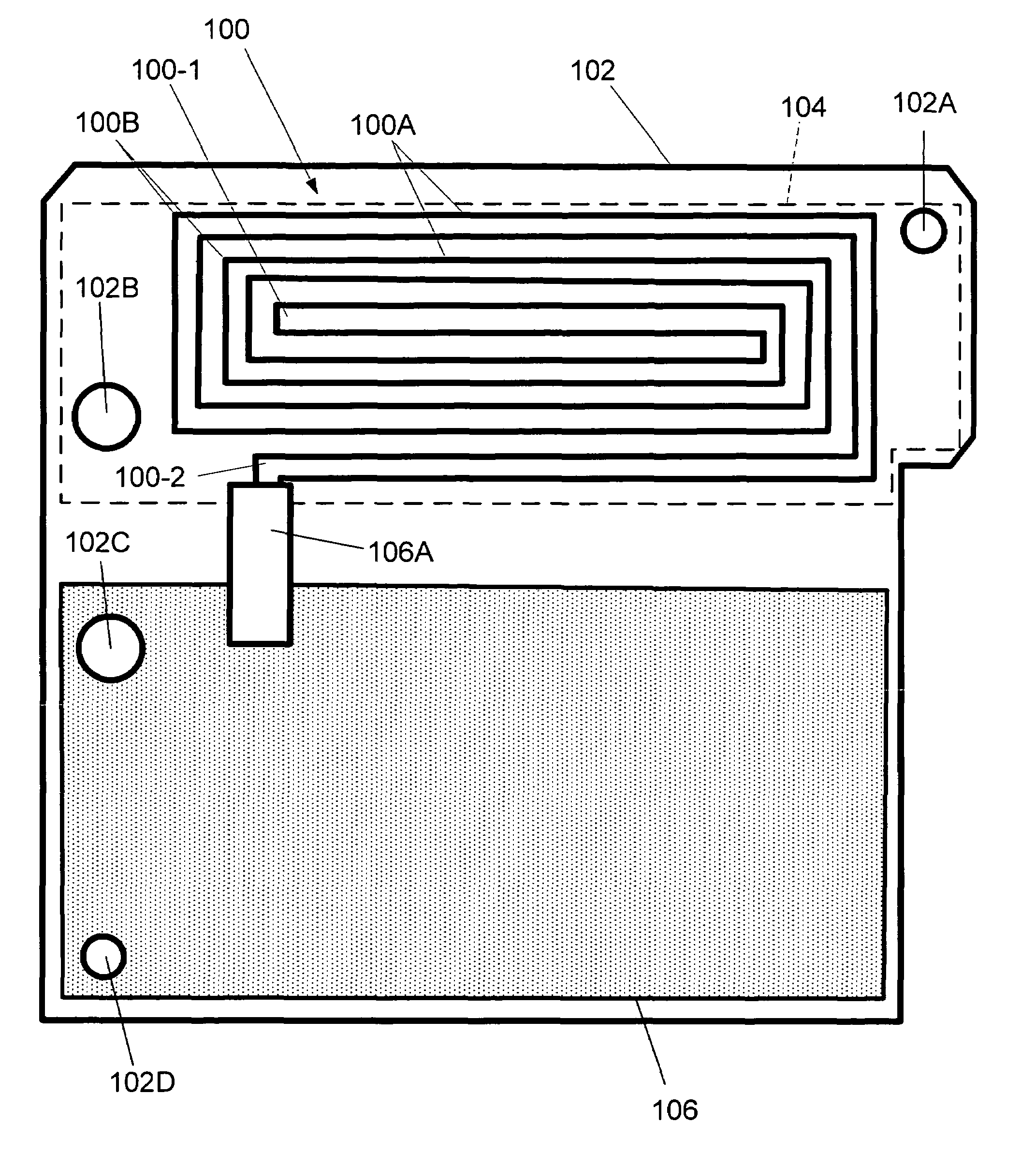
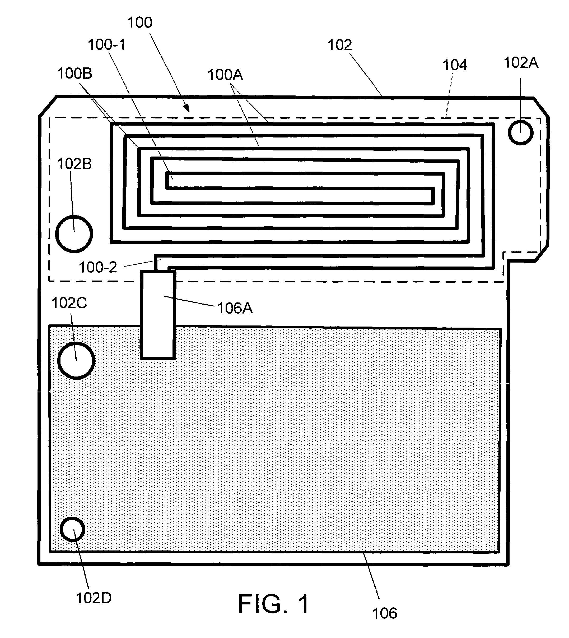
[0022]FIG. 1 shows an embodiment of the invention which comprises a square spiral shape antenna 100 which is printed directly on a first side of a substrate / board 102 such as PCB (printed circuit board). A ground plane 104 is formed on a second opposite side of the PCB 102. In this embodiment, the ground plane 104 is formed opposite the antenna 100. The square spiral antenna 100 is dimensioned to fit on the PCB 102 in a manner which is not only compact but which provides accurate reception to RF (Radio. Frequency) signals in the desired frequency. In this embodiment the RF is approximately 315 MHz.

[0023]As shown, this antenna 100 has straight portions 100A and corner portions 100B. In this arrangement the straight portions 100A have a width to total antenna length ratio of about 1 / 20. The antenna 100 is, in this embodiment, formed of copper and is printed onto the PCB 102. It should be noted that the invention is not limited to the use of copper irrespective of the fact that it has ...


PUM


Abstract

An antenna arrangement for a RF (radio frequency) signal, has: printed circuit board having first and second opposed sides; a ground plane formed on the first side of the printed circuit board; a circuit disposed on the second side of the printed circuit board; and a flat, polygonal shaped spiral member disposed on the second side of the printed circuit board, the polygonal shaped spiral member a first free end a second connection end connected to the circuit, the spiral member having a plurality of straight portions which are interconnected to form a plurality of corners.

Description

FIELD OF THE INVENTION[0001]The present invention relates generally to antenna and more specifically to a microstrip antenna for an RF receiver suitable for use in compact arrangements.BRIEF DESCRIPTION OF THE RELEVANT ART[0002]In the past, systems have used printed trace antennas or separate antenna components which are attached to the PCB (Printed circuit board). However, these arrangements have suffered from drawbacks such as the component antenna increasing cost, weight and suffering from the tendency for failure when used in an RF system. The printed antennas, on the other hand, have space consuming configurations. One example of these is the conical configuration is three dimensional and tends to consume a lot of space and has thus proven problematical when applied in situations wherein space is at a premium such as in automotive keyless entry and tire pressure monitoring systems.SUMMARY OF THE INVENTION[0003]The present invention is directed to a spiral shape antenna which ca...

Claims


Application Information

Patent Timeline
Patent Type & Authority Patents(United States)
IPC IPC(8): H01Q1/36H01Q1/38
CPCB60C23/0444
Inventor BRANDWEIN, JR., RICHARD PAUL
Owner OMRON AUTOMOTIVE ELECTRONICS CO LTD
Why Eureka
Try Eureka