Shared buffer type variable length packet switch

a packet switch and variable length technology, applied in the field of packet switches, can solve the problems of low packet switching speed, and low buffer memory use efficiency

Inactive Publication Date: 2005-12-20
HITACHI LTD
View PDF5 Cites 34 Cited by
  • Summary
  • Abstract
  • Description
  • Claims
  • Application Information

AI Technical Summary

Benefits of technology

[0018]In the second embodiment, each of said output queue is constructed by, for example, a standby buffer for temporarily storing therein write addresses of a head data block and the last data block of a variable length packet, and an address memory for storing therein a next read address and a last read address indicative of the next data block and the last data block. The first control means registers a write address of a head data block and a write address of a last data block of a variable length packet into said standby buffer corresponding to the destination output line. When the address memory associated with the standby buffer enters an idle state, said second control means sets a pair of write addresses obtained from the standby buffer into the address memory as a next read address and a last read address of a new data block group. In this case, the second control means reads out a fixed length data block and the address of a next fixed length data block from said shared buff

Problems solved by technology

There is consequently a problem that the packet switching speed is low.
Furthermore, since each of the line cards on the input side needs a buffer for temporarily storing the packets, and each of the line cards on the output side also needs a bu

Method used


Image

  • Shared buffer type variable length packet switch
  • Shared buffer type variable length packet switch
  • Shared buffer type variable length packet switch

Examples


first embodiment

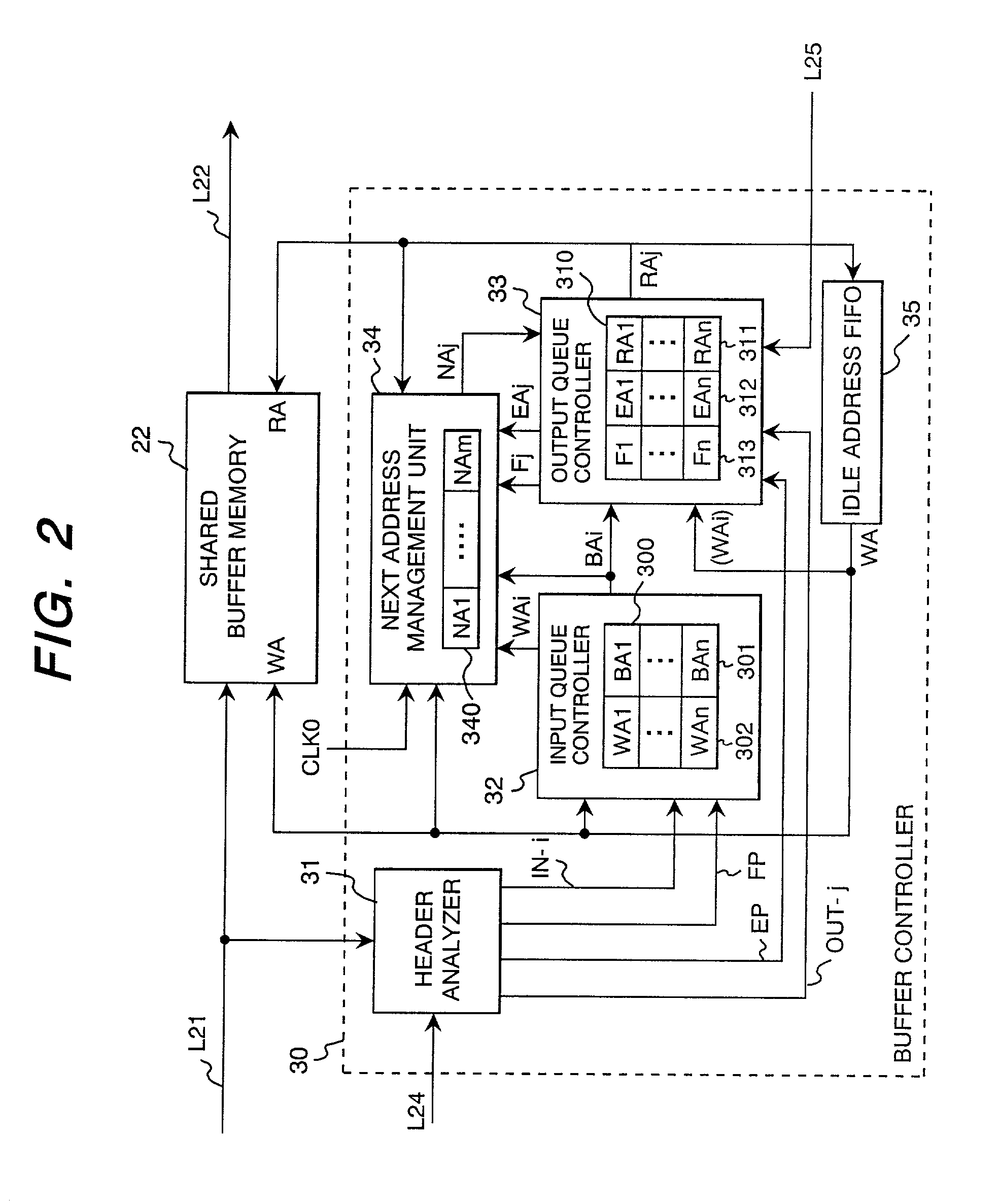
[0044]FIG. 2 is a block diagram showing the buffer controller 30. The buffer controller 30 includes a header analyzer 31, an input queue controller 32, an output queue controller 33, a next address management unit 34, and an idle address memory (FIFO) 35 for storing idle addresses of the shared buffer memory 22.

[0045]The header analyzer 31 analyzes the internal header of each data block appearing on the signal line L21 and generates input line number IN-i, output line number OUT-j, a head indication flag signal FP indicating whether the input data block is the first block of the received packet or not, and a tail indication flag signal EP indicating whether the input data block is the last block of the received packet or not.

[0046]The input queue controller 32 has an input queue address table 300 showing, for each input line, an address 301 (packet head address BAi (i=1 to n) ) of the first data block registered in the input queue and an address 302 of the latest data block (latest ...

third embodiment

[0102]FIG. 15 shows the buffer controller 30 having a broadcasting or multicasting function of transferring the same packet to a plurality of output lines. The buffer controller 30 shown here has, in a manner similar to the buffer controller 30 of the second example shown in FIG. 9, the header analyzer 31, input queue controller 32, output queue controller 33B, next address management unit 34B, and idle address FIFO 35 and has, as a new element, a read address release controller 36.

[0103]Each of the input line interfaces 10-i (i=1 to n) adds an internal header for designating a plurality of output lines to each of data blocks obtained by dividing a received packet from the input line LI-i when the received packet is a broadcast (multicast) packet to be forwarded to a plurality of output lines. In order to designate a plurality of output lines at the same time, for example, it is preferable to employ a bit pattern as the contents of the output line number field in the internal header...

second embodiment

[0108]The addresses BAi and WA set in the output standby buffers 330-1 to 330-n are, in a manner similar to the second embodiment, transferred to the next read address registers 311-1 to 311-n and the last read address registers 312-1 to 312-n. In accordance with the read address RAj indicated by the next read address registers 311-1 to 311-n, the data blocks are read out from the shared buffer memory 22. Regarding data blocks belonging to a broadcast packet, as described above, the same linked address list is registered in a plurality of output queues, the same data block is repeatedly read out a plurality of times.

[0109]In the first and second embodiment directed only for a uni-cast packet, as shown in FIGS. 2 and 9, it is sufficient to release the read address RAj to the idle address FIFO 35 when a data block is read out from the shared buffer memory 22. In contrast, in the case where broadcast packets are processed as in the third embodiment, it is necessary to confirm the compl...


PUM


Abstract

A packet switch having a structure of writing a variable length packet received from each of input lines into a shared buffer memory on a fixed length data block unit basis, wherein a buffer controller forms an input queue for each input line and, when the last data block of a variable length packet is registered in the input queue, links a linked address list for the input queue to one or a plurality of output queues corresponding to one or a plurality of packet destination output lines.

Description

BACKGROUND OF THE INVENTION[0001](1) Field of the Invention[0002]The present invention relates to a packet switch applied as a node apparatus in a variable length packet communication network and, more particularly, a shared buffer type variable length packet switch using a shared buffer memory as a memory for temporarily storing received packets.[0003](2) Description of the Related Art[0004]In recent years, in the Internet protocol (IP) to which attention is paid, a message is transferred by using a variable length packet (IP packet) called IP datagram as a transfer unit. In a conventional node apparatus as an element of an IP packet network, received packets are switched to a destination path by a software process. To address a demand on higher speed of switching, a node apparatus for switching a packet by using a fixed length packet (data block) as a transfer unit has been proposed.[0005]As a node apparatus for transferring IP packets at high speed, for example, the paper of “A 5...

Claims


Application Information

Patent Timeline
IPC IPC(8): H04L12/56
CPCH04L49/103H04L49/3018H04L49/3027H04L49/351H04L49/40
Inventor TAKAHASHI, MASAMIMAKIMOTO, AKIOKOZAKI, TAKAHIKOKANNO, TAKAYUKIOGINUMA, YASUONAKAYAMA, KAORIWADA, MITSUHIROMORIWAKI, NORIHIKOFUKANO, MASUMIFUTAMI, YUSHO
Owner HITACHI LTD
Why Eureka
Try Eureka