Apparatus for cleaving optical fiber

a technology of optical fiber and apparatus, applied in the direction of optical elements, instruments, transportation and packaging, etc., can solve the problems of increasing the volume of the apparatus, decreasing the work efficiency, and increasing the working time, and achieve the effect of increasing work efficiency and simple structur

Inactive Publication Date: 2005-12-20
SAMSUNG ELECTRONICS CO LTD
View PDF32 Cites 32 Cited by
  • Summary
  • Abstract
  • Description
  • Claims
  • Application Information

AI Technical Summary

Benefits of technology

[0010]Accordingly, it is an aspect of the present invention to provide an apparatus to cleave an optical fiber, wherein the apparatus has a simple structure, thus increasing work efficiency.
[0018]According to an aspect of the invention, the gripper is partially covered with silicone to prevent the optical fiber from being damaged while clamping the optical fiber.

Problems solved by technology

However, in most of the conventional apparatuses for cleaving the optical fiber, stripping, cleaning and cleaving processes are independently performed by separate units, increasing working time, and thus decreasing work efficiency.
Therefore, the volume of the apparatus is increased, and the structure is more complicated, prolonging working time and decreasing work efficiency.
However, it is inconvenient for a user to replace the cutter with a new one using the conventional apparatus for cleaving the optical fiber.

Method used


Image

  • Apparatus for cleaving optical fiber
  • Apparatus for cleaving optical fiber
  • Apparatus for cleaving optical fiber

Examples


Embodiment Construction

[0031]Reference will now be made in detail to the embodiments of the present invention, examples of which are illustrated in the accompanying drawings, wherein like reference numerals refer to like elements throughout. The embodiments are described below in order to explain the present invention by referring to the figures.

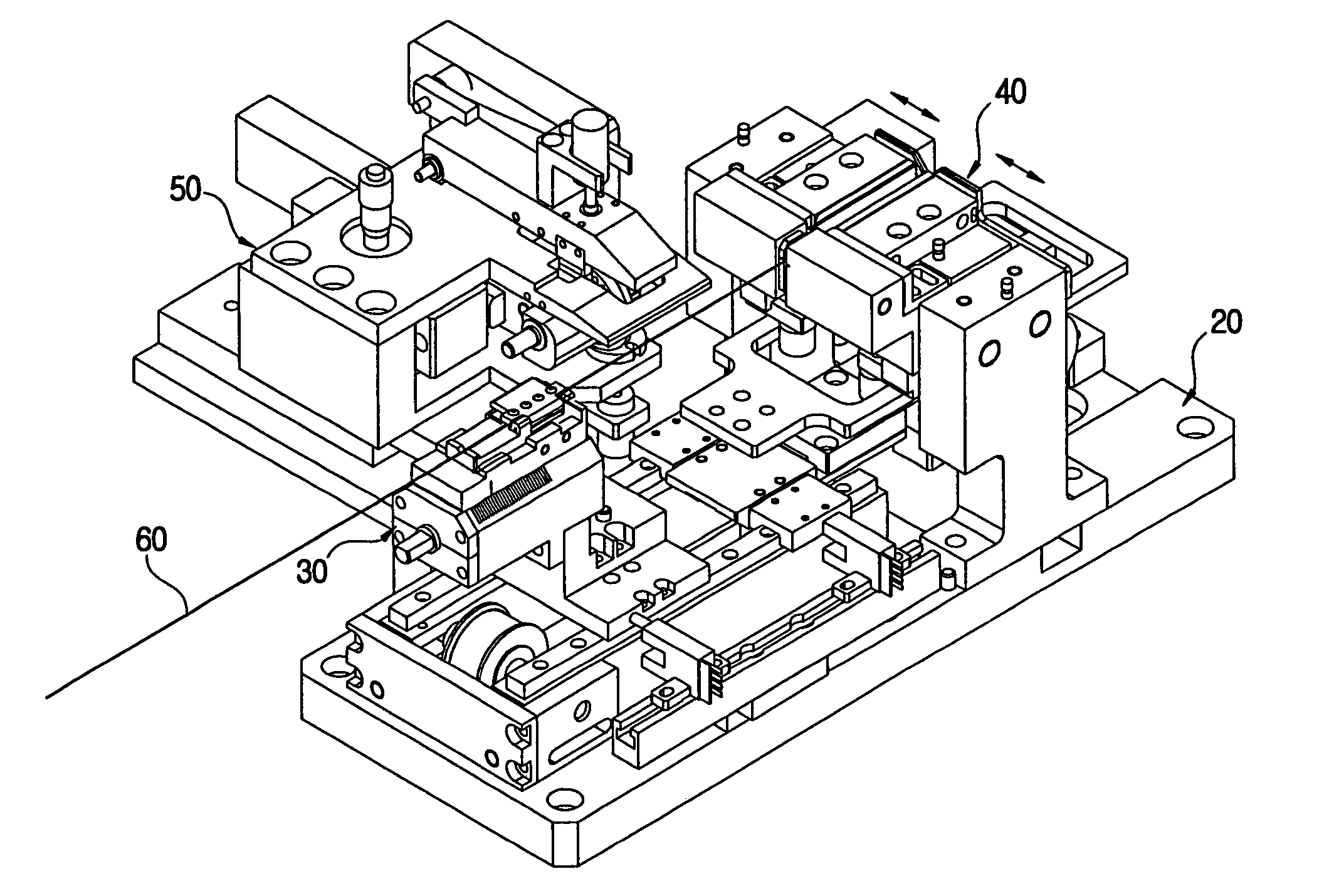
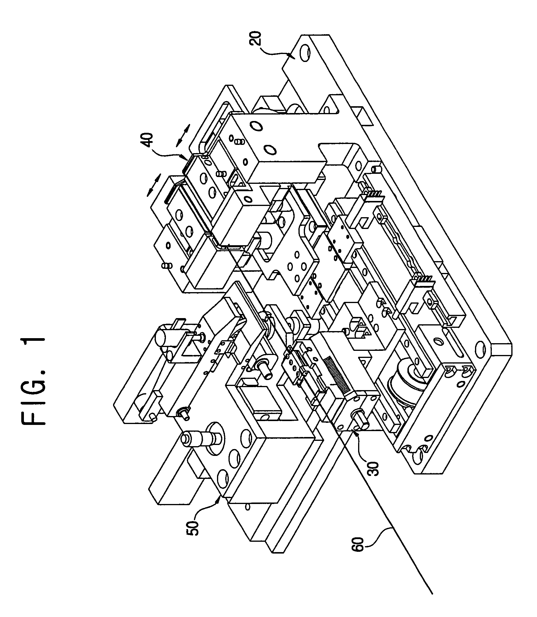
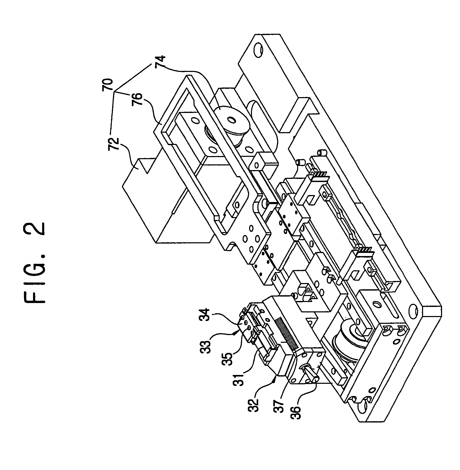
[0032]As shown in FIGS. 1 through 3, an apparatus according to an embodiment of the present invention to cleave an optical fiber comprises a base plate 20, a jig 30 slidably provided on the base plate 20 and holding an optical fiber 60, a stripper 40 provided with a hot plate 42 heating a sheath of the optical fiber 60, a sheath cutter 44 cutting the sheath of the optical fiber 60 to be stripped, a cleaning part 46 cleaning the optical fiber 60 after the sheath of the optical fiber 60 is stripped as the jig 30 slides, and a cleaver 50 provided on the base plate 20 and cleaving the optical fiber 60 whose sheath is stripped by the stripper 40. The base plate 20 supp...


PUM


Abstract

An apparatus to cleave an optical fiber includes a base plate, a jig slidably provided on the base plate and holding the optical fiber, a stripper provided near the jig, and including a hot plate heating a sheath of the optical fiber, a sheath cutter cleaving the sheath of the optical fiber to be stripped, a cleaning part cleaning the optical fiber after the sheath of the optical fiber is stripped according as the jig slides, and a cleaver provided on the base plate and cleaving the optical fiber whose sheath is stripped by the stripper. With this configuration, an apparatus is provided to cleave an optical fiber, in which stripping and cleaning processes are simultaneously performed in a stripper, so that the whole process of cleaving the optical fiber is decreased, and the structure of the apparatus is simplified without the conventional cleaning part.

Description

CROSS-REFERENCE TO RELATED APPLICATIONS[0001]This application claims the benefit of Korean Patent Application No. 2002-83346, filed Dec. 24, 2002, in the Korean Intellectual Property Office, the disclosure of which is incorporated herein by reference.BACKGROUND OF THE INVENTION[0002]1. Field of the Invention[0003]The present invention relates to an apparatus for cleaving an optical fiber, and more particularly, to an apparatus for cleaving an optical fiber, wherein the apparatus quickly and precisely cleaves the optical fiber.[0004]2. Description of the Related Art[0005]Optical fibers are connected to each other and branched off by an optical coupler or an optical connector, which requires precisely cleaved optical fibers.[0006]Generally, in a conventional apparatus for cleaving the optical fiber, a sharp blade first makes a cleaved line on a cladding of the optical fiber, and then the optical fiber is pulled in opposite directions, thus cleaving the optical fiber in the cleaved lin...

Claims


Application Information

Patent Timeline
Patent Type & Authority Patents(United States)
IPC IPC(8): G02B6/00G02B6/245G02B6/25
CPCG02B6/245G02B6/25Y10T225/20Y10T225/217Y10T225/218Y10T225/307
Inventor HWANG, MYEON-SOONKIM, BYUNG-GONSUN, HONG-SUK
Owner SAMSUNG ELECTRONICS CO LTD
Why Eureka
Try Eureka