
Fuel injection controlling apparatus for engine

a technology of controlling apparatus and fuel injection, which is applied in the direction of mechanical equipment, electric control, machines/engines, etc., can solve the problems of increasing soot in oil, mixing air and fuel not easily uniform, and fuel consumption getting deteriorated, so as to achieve the effect of further reducing the amount of fuel injection

Inactive Publication Date: 2005-12-27
KOMATSU LTD
View PDF11 Cites 2 Cited by
  • Summary
  • Abstract
  • Description
  • Claims
  • Application Information

AI Technical Summary

Benefits of technology

[0011]In view of the problems described above, the invention is directed to provide a fuel engine injection controlling apparatus for an engine that decreases the amount of NOx in the exhaust and needs less fuel consumption.
[0013]According to the first invention, in the Diesel engine including the first fuel injection means provided to the cylinder and the second fuel injection means provided to the intake passage, the second fuel injection means injects the fuel in the low engine load zone. Therefore, pre-mixing uniform combustion can be acquired in the low load zone, and the generation amounts of NOx can be drastically reduced. In the high load zone, on the other hand, the first fuel injection means injects the fuel into the cylinders. Therefore, stable combustion can be acquired.
[0015]According to the second invention, the fuel is injected to both of the cylinder and the intake passage in the predetermined boundary zone between the high load zone and the low load zone. Therefore, when the engine load passes by the boundary between the high load zone and the low load zone, a drastic change between combustion by the injection into the cylinder and combustion by injection into the intake passage can be mitigated, the occurrence of torque fluctuation becomes less and a smooth engine operation can be conducted.
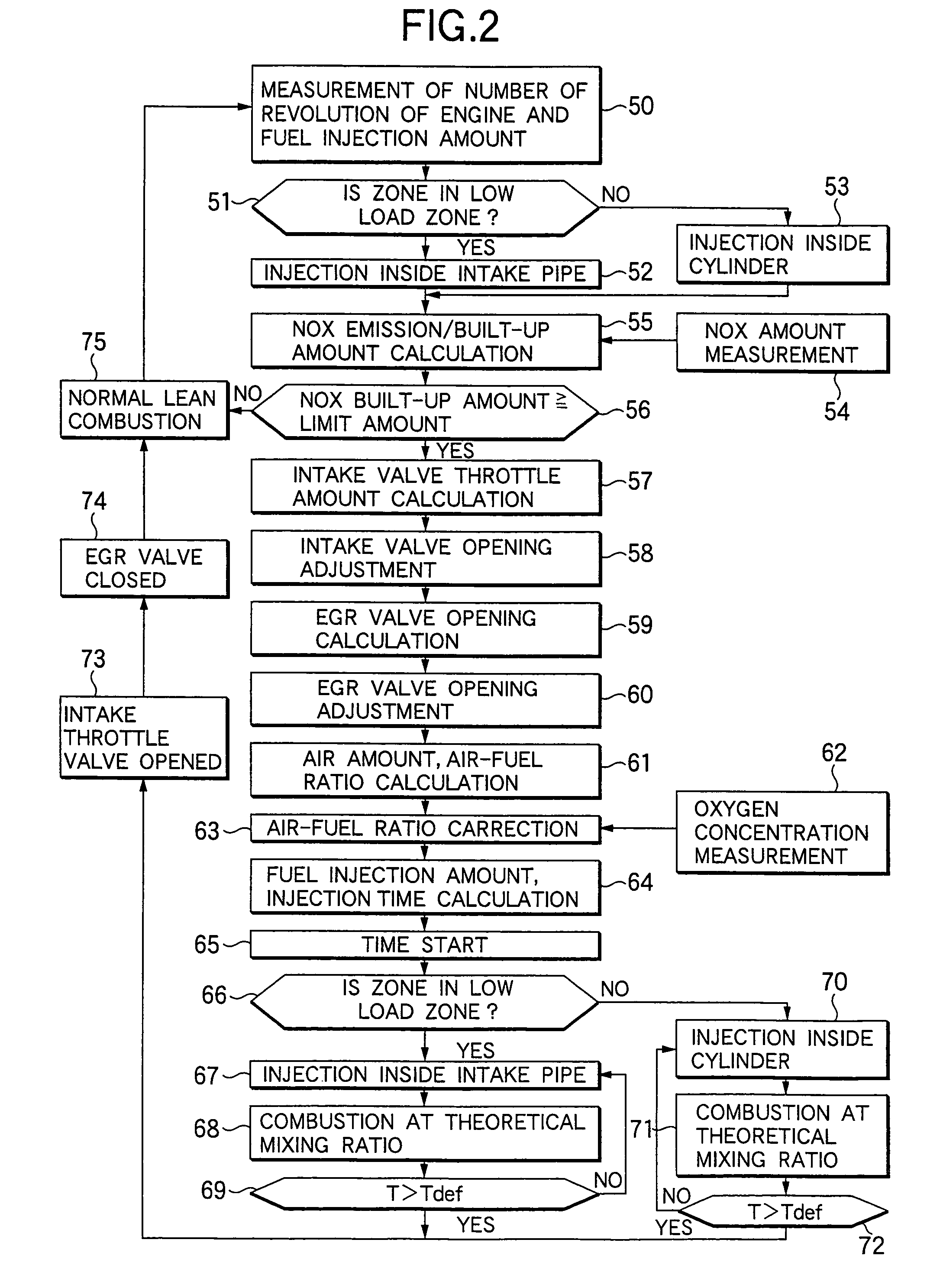
[0017]The third invention includes the NOx absorption / reduction catalyst in addition to the fuel injection controlling apparatus having a small amount of NOx in the exhaust gas at the low engine load. Therefore, the NOx absorption / reduction catalyst need not be big in size. When the air-fuel ratio of the exhaust gas is rendered rich in the low load zone, the second fuel injection means injects the fuel into the intake passage so that the air-fuel ratio attains a ratio approximate to the theoretical mixing ratio. Since a uniform air-fuel mixture can be obtained and pre-mixing combustion is conducted, the generation amounts of NOx can be reduced, and deterioration of a fuel consumption ratio and abnormal high temperature inside the combustion chamber can be avoided.
[0019]The fourth invention can decrease the intake air amount when intake air is throttled. Therefore, the overall air amount becomes small, and deterioration of the fuel consumption ratio when the air-fuel ratio of the exhaust gas is rendered rich can be further decreased.
[0021]Since the exhaust gas-recirculation device is disposed according to the fifth invention, the air-fuel ratio of the exhaust gas can be rendered rich when the exhaust gas is recirculated. Therefore, the fuel injection amount can be further reduced and combustion can be stabilized.

Problems solved by technology

However, the constructions described above involve the following problems.
In consequence, large amounts of the fuel directly adhere to the inner wall of a cylinder liner and are carbonized to thereby increase soot in oil.
Since large amounts of the fuel are injected into the cylinder within a short time, mixing of air and the fuel does not easily become uniform, and fuel consumption gets deteriorated.
In addition, the amount of the fuel injected to the intake system increases and fuel consumption gets deteriorated.

Method used


Image

  • Fuel injection controlling apparatus for engine
  • Fuel injection controlling apparatus for engine
  • Fuel injection controlling apparatus for engine

Examples


first embodiment

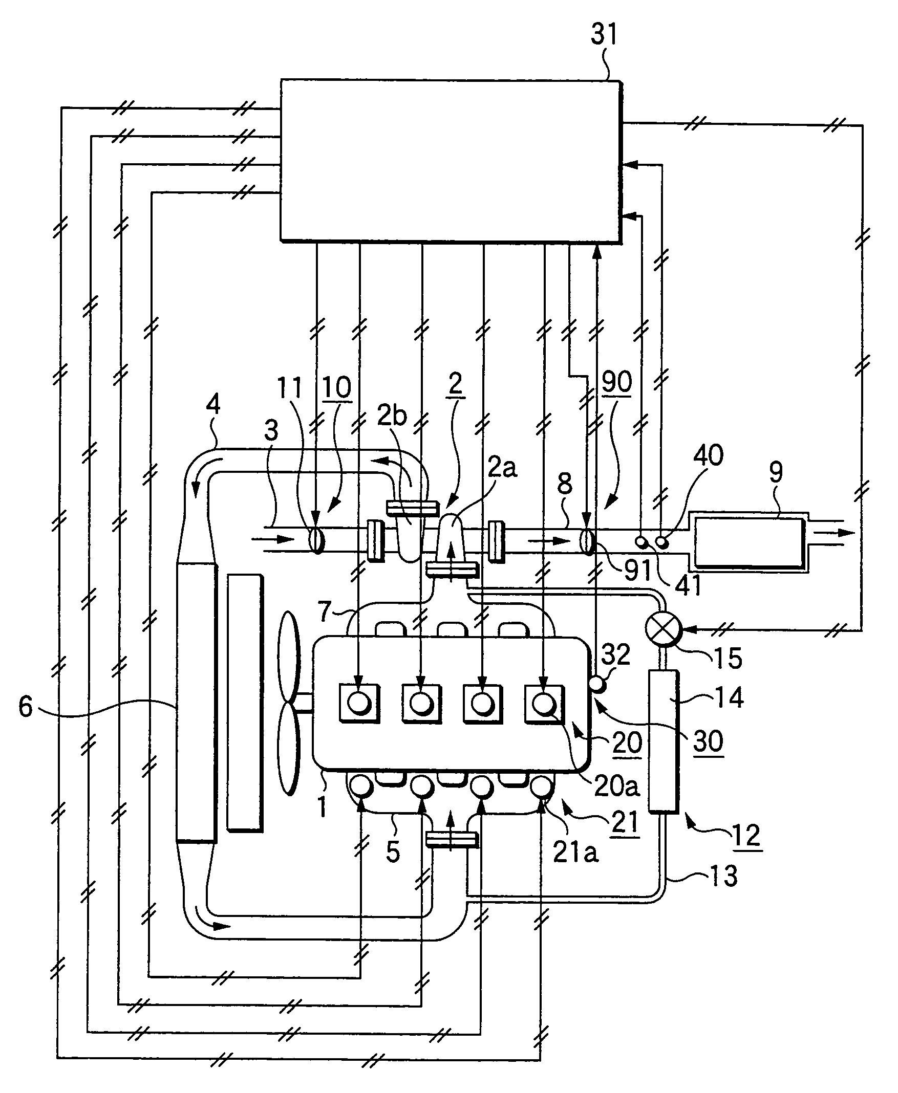
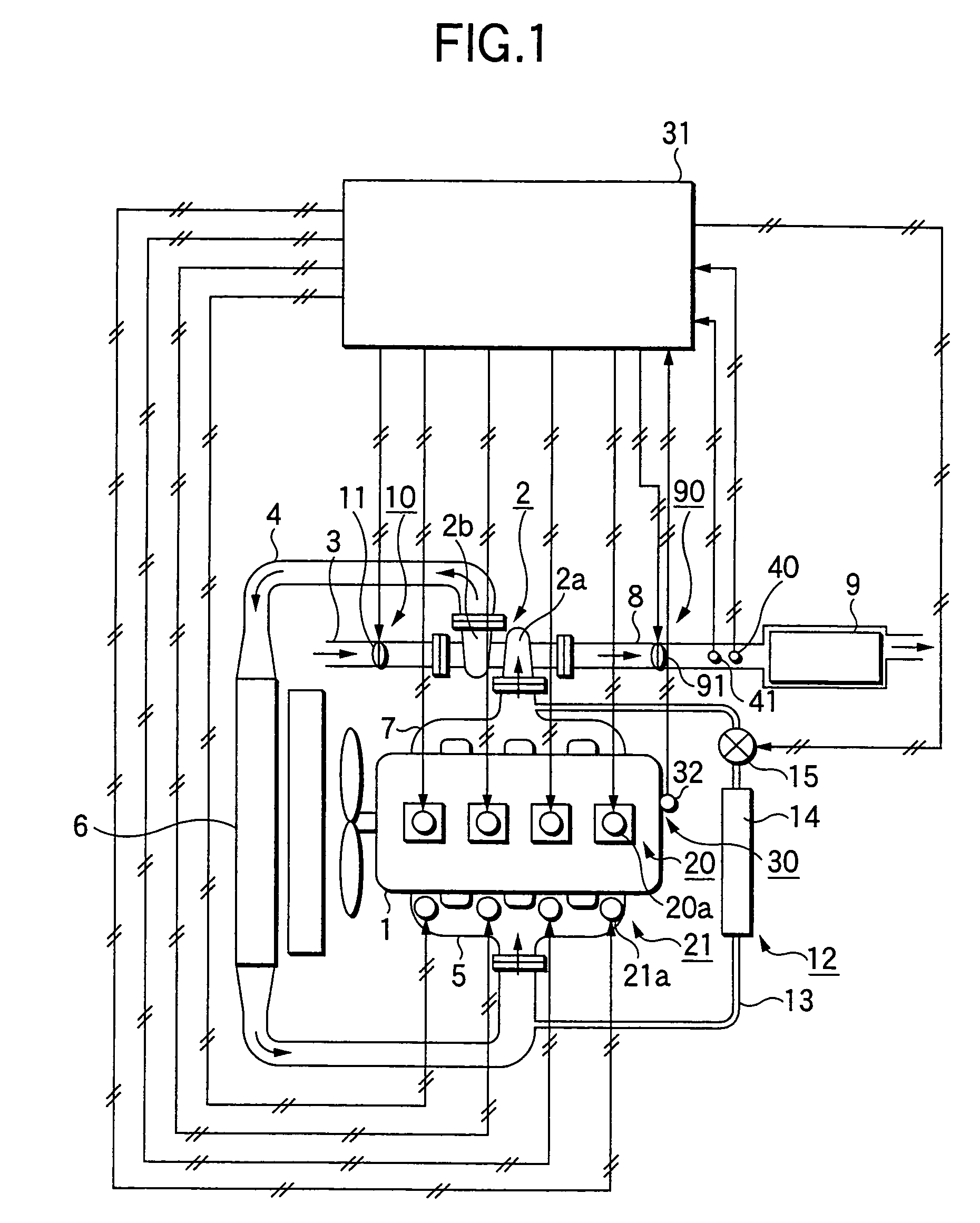
[0027]FIG. 1 is a conceptual view of a Diesel engine with a denitration device, which engine has a fuel injection controlling apparatus for an engine according to the invention. An engine 1 includes a turbo charger 2. The turbo charger 2 includes an exhaust turbine 2a and a compressor 2b. The exhaust turbine 2a is fitted to an exhaust manifold 7. An exhaust pipe 8 is fitted to an exhaust port of the exhaust manifold 7. A NOx absorption / reduction catalyst 9 is inserted to the exhaust pipe 8. An intake pipe 3 is fitted to an intake port of the compressor 2b interconnected to the exhaust turbine 2a. An intake throttle valve 11 that constitutes intake throttle means 10 capable of regulating an open area is fitted to the intake pipe 3. A feed pipe 4 is fitted to the exhaust port of the compressor 2b and is thence connected to the intake manifold 5. An inter-cooler 6 is inserted into the feed pipe 4. The part of the feed pipe downstream of the inter-cooler 6 and the part of the exhaust ma...

third embodiment

[0066]In the third embodiment, the fuel injection amount is detected from the detection signal of the rack position sensor but it may be detected from a fuel control lever or from a stroke of an acceleration pedal. In the case of a common l type fuel injection apparatus, the fuel injection amount be detected by controlling the opening / closing time of a tree-way valve of the injection nozzle.


PUM


Abstract

The invention provides a fuel injection controlling apparatus for an engine that reduces NOx amounts in an exhaust gas of a Diesel engine conducting lean combustion. An inter-cylinder injector (20a) is arranged in each cylinder of an engine (1). An intake port / manifold injector (21a) is arranged at an inlet of each cylinder of an intake manifold (5). A speed sensor (32) for detecting the engine speed is provided to the engine. A controller (31) is connected to the speed sensor (32), the inter-cylinder injector (20a) and the intake port / manifold injector (21a), and calculates an engine load. The intake port / manifold injector (21a) injects the fuel when the engine load is low, and the inter-cylinder injector (20a) injects the fuel when the engine load is high.

Description

CROSS-REFERENCE TO RELATED APPLICATION I[0001]This application is a continuation application of U.S. Ser. No. 10 / 101,866 filed on Mar. 21, 2002, now U.S. Pat. No. 6,813,880.BACKGROUND OF THE INVENTION[0002]1. Field of the Invention[0003]This invention relates to a fuel injection controlling apparatus for reducing NOx amounts in an exhaust gas of a Diesel engine that executes lean combustion.[0004]2. Description of the Related Art[0005]Various proposals have been made in the past to reduce amounts of NOx contained in an exhaust gas of a Diesel engine. For instance, Japanese Patent Laid-Open Nos. 218920 / 1996 and 358717 / 1992 describe one of such proposals.[0006]The proposal described in Japanese Patent Laid-Open No. 218920 / 1996 arranges a NOx absorbing agent that normally absorbs NOx, renders an air-fuel ratio of an exhaust gas rich, and emits and reduces NOx when the built-up amount exceeds a limit. When NOx is to be emitted from the NOx absorbing agent, an engine control circuit lowe...

Claims


Application Information

Patent Timeline
IPC IPC(8): F01N3/08F02M25/07F01N3/24F02D9/02F02D9/04F02D9/10F02D11/10F02D21/08F02D41/02F02D41/04F02D41/30F02D41/38F02D43/00F02D45/00F02M63/00
CPCF01N3/0842F02D41/0275F02D41/1458F02D41/1462F02D41/3035F02D41/3094F02B29/0425F02D41/005F02D41/0055F02D41/1454F02D2041/0017F02D2200/0614F02M25/0707F02M25/0713F02M25/0727F02M26/05F02M26/10F02M26/23
Inventor NISHIYAMA, TOSHIHIKOWAKAMOTO, KOUTAROU
Owner KOMATSU LTD
Learn More