

Handlebar throttle controller with hysteresis
a controller and handlebar technology, applied in the direction of mechanical control devices, instruments, cycle equipments, etc., can solve the problems that the operation and feel of such spring-biased handlebar throttle controllers remains significantly different from mechanical throttle linkages, and achieve the effect of simple mechanical design and better operator control of the throttl
- Summary
- Abstract
- Description
- Claims
- Application Information
AI Technical Summary
Benefits of technology
Problems solved by technology
Method used
Image

Examples
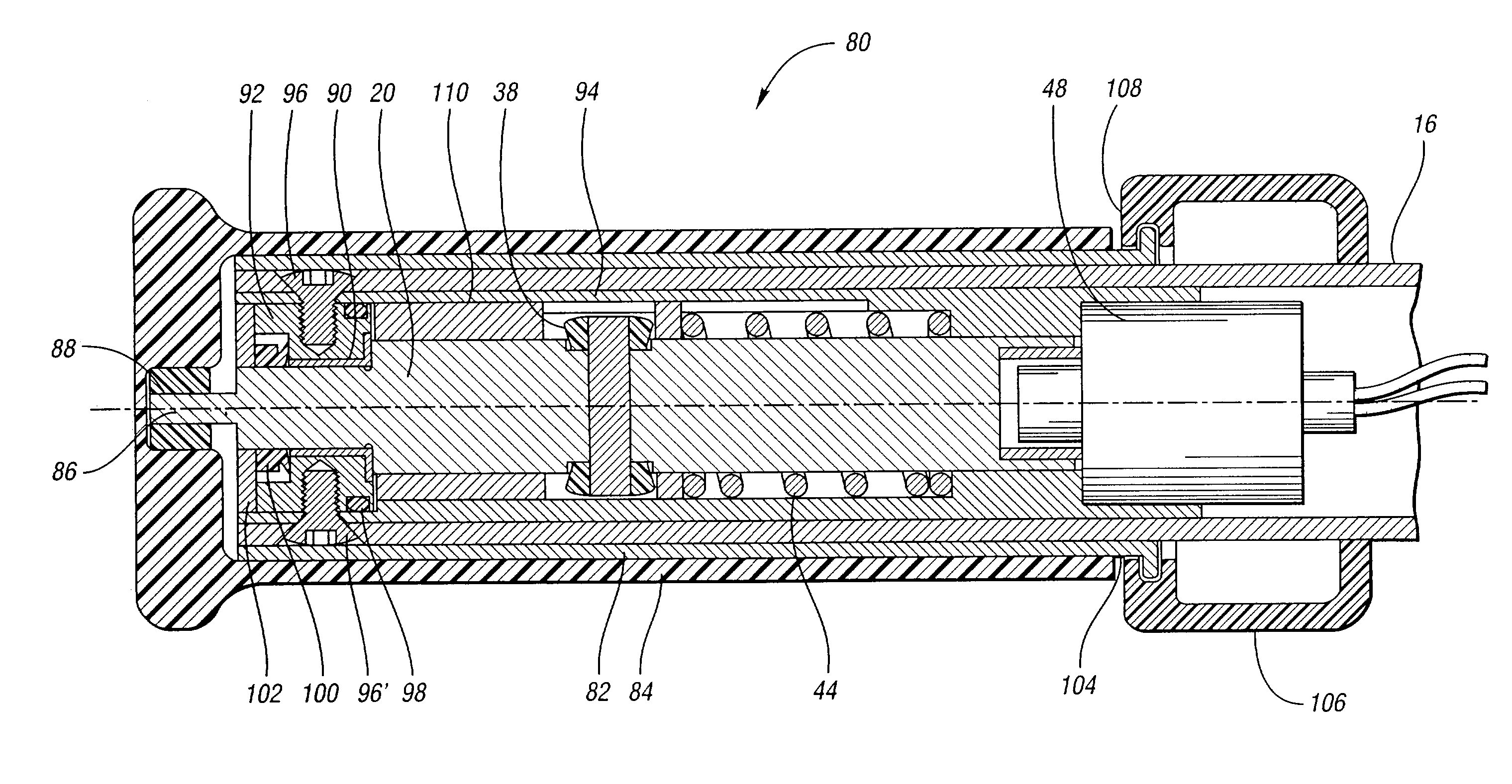
embodiment 80
[0035]A fourth throttle controller embodiment 80 is shown in FIG. 8. Since the throttle grip is conventionally located on the right hand side of an internal combustion engine driven vehicle with steering handles, FIG. 8 may illustrate a section view wherein the viewer's perspective is facing the vehicle. Of course, the invention contemplates use of a throttle controller on any handle, regardless of side or orientation.
[0036]Throttle controller 80 is substantially similar to throttle controller 10 illustrated in FIGS. 1 and 2. Throttle controller 80, being more refined and production ready in design, is provided with seals to maintain the throttle controller 80 in a watertight condition. The throttle controller 80 is also provided with means for attachment to a motorcycle handlebar 16. The grip member of the throttle controller 80 is formed of a rigid plastic inner component 82 and a soft rubber-like outer component 84 which rotate together about the distal end of handlebar 16.
[0037]...
sixth embodiment
[0042]the present invention is illustrated by throttle control 140 in FIG. 11. Throttle control 140 differs primarily from throttle controller 120 of FIG. 10 by the fact that it is located externally, in this example coaxially about handlebar 16, rather than within the internal cavity formed within the handlebar. The spring and cam mechanism of throttle control 140 is housed within switch housing 106. The throttle control includes a grip assembly 142 which fits over the end of handlebar 16 for free rotation and limited axial movement relative thereto in a manner described with reference to FIG. 8 previously. The end of the grip assembly 142 within the switch housing 106 is provided with notches or splines which engage a rotary cam 144. Rotary cam 144 is provided with a pair of cam slots 146 in a manner similar to cam 130 in FIG. 10. Rotary cam 144 is supported upon a bearing 148 and a stop ring 150, which are affixed to the handlebar 16. As the rotary cam 144 rotates with the grip a...
PUM
 Abstract
Description
Claims
Application Information