Railway car and bogie of railway car

a railway car and bogie technology, applied in the field of passenger railway cars, can solve the problems of vibration generation, uncomfortable ride quality, and conventional passenger railway cars

Inactive Publication Date: 2005-12-27
HITACHI LTD
View PDF10 Cites 19 Cited by
  • Summary
  • Abstract
  • Description
  • Claims
  • Application Information

AI Technical Summary

Benefits of technology

[0006]The object of the present invention is to provide an inexpensive car body with low noise.
[0008]According to this arrangement, the car body can rotate freely with respect to the subframe when needed, and thereafter, such as when the tracks return straight, the car body rotates again with respect to the subframe so that the relative positional relationship between the subframe and car body is returned to its original state.

Problems solved by technology

Patent Document 1: Japanese Patent Laid-Open No. 04-173472 The drawbacks of the conventional passenger railway car are noise and uncomfortable ride quality.
One cause of the noise is the vibration generated at the bogie which is transmitted to the car body via the center pin.
Further, the elastic member in the coupling device connecting one car body with the adjacent car body is capable of sliding with respect to the car body, and at this portion, the coupling device may collide against the car body by the vertical and horizontal movement of the car body caused by the irregularity of the rail track, which also causes noise and vibration.
However, such welding operation is not easy since strain is often caused by the process.

Method used


Image

  • Railway car and bogie of railway car
  • Railway car and bogie of railway car
  • Railway car and bogie of railway car

Examples


Embodiment Construction

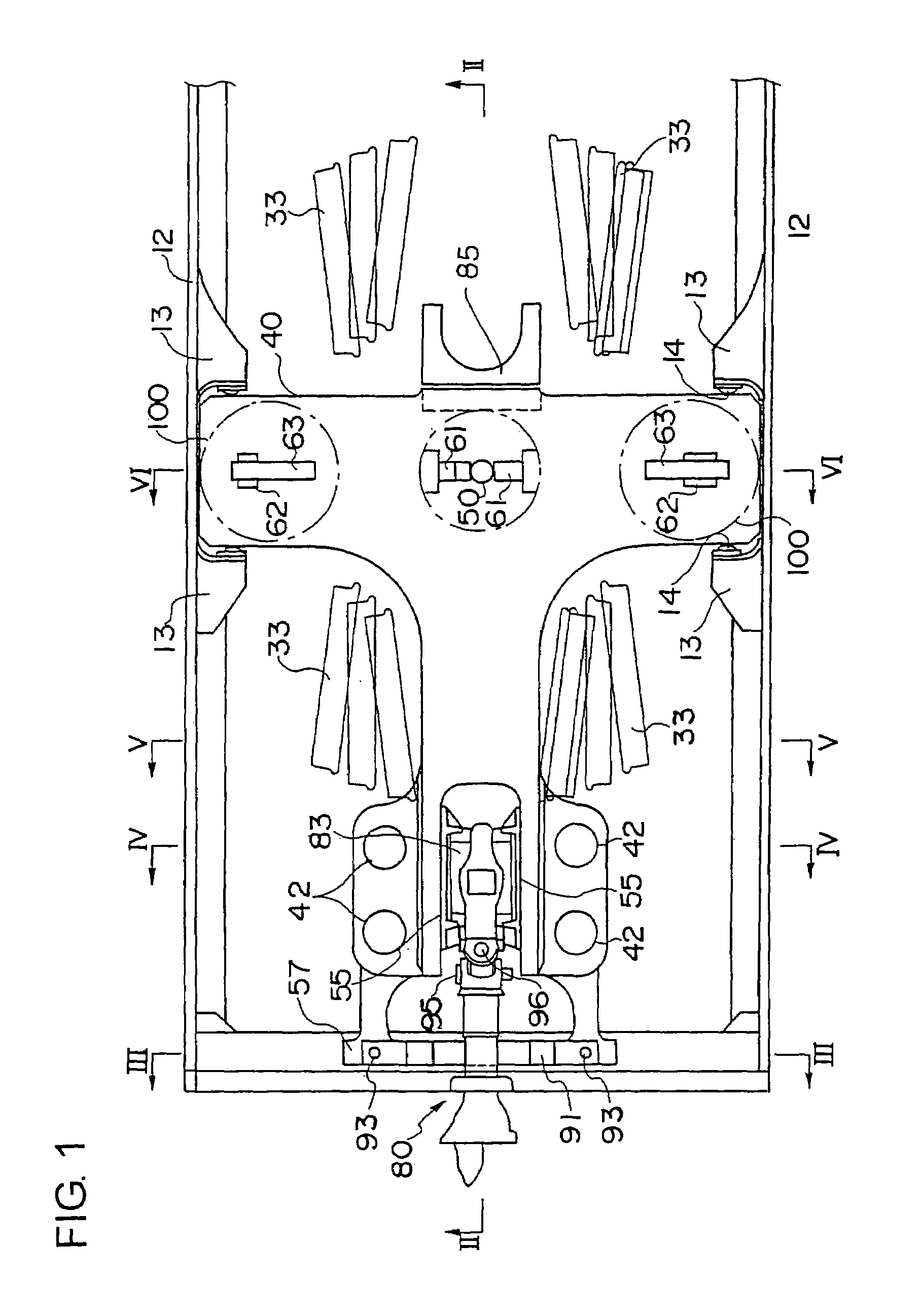
[0018]One preferred embodiment of the present invention will be explained with reference to FIGS. 1 through 9. FIG. 1 is a plan view showing the car body 10 with the floor 11 omitted.

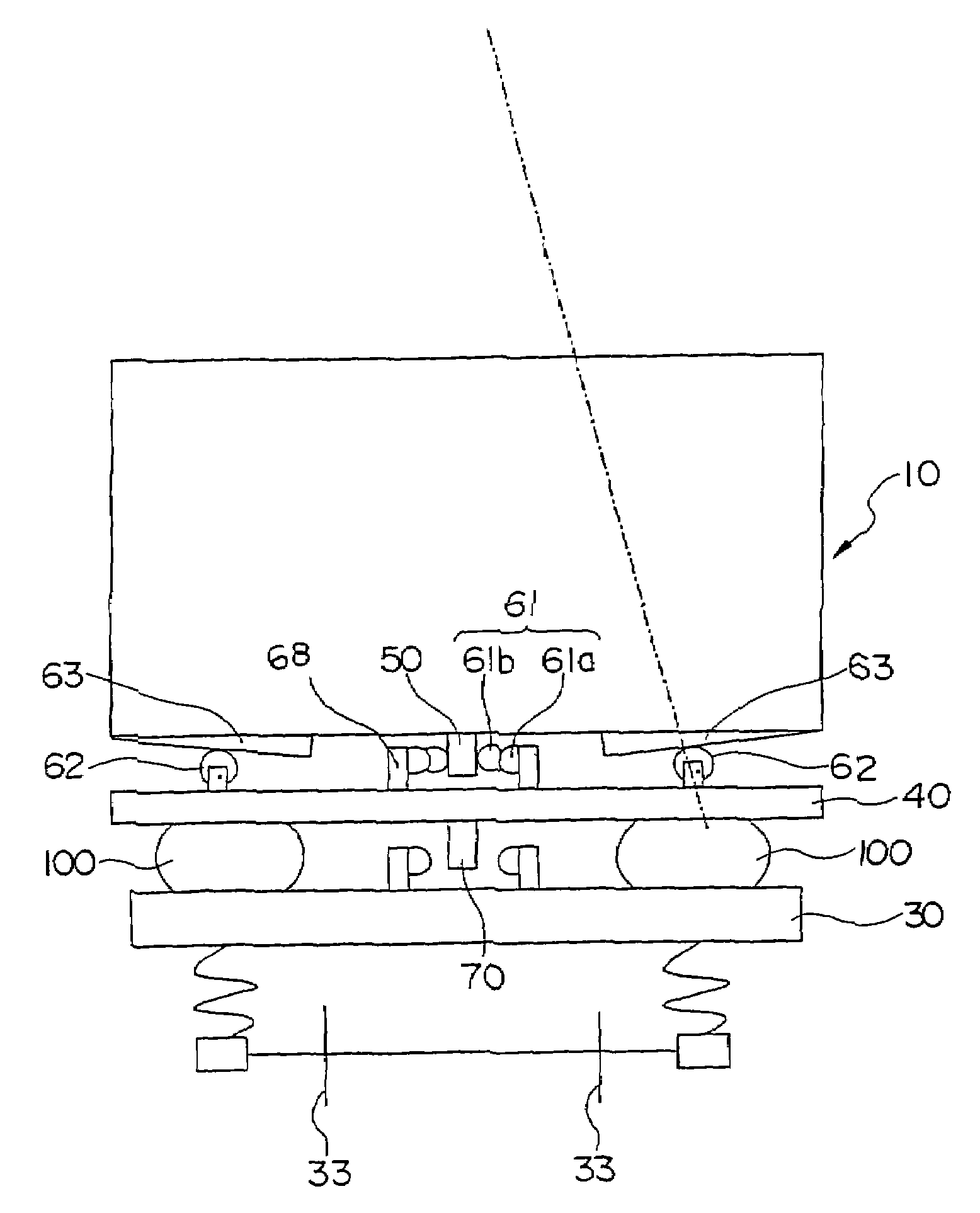
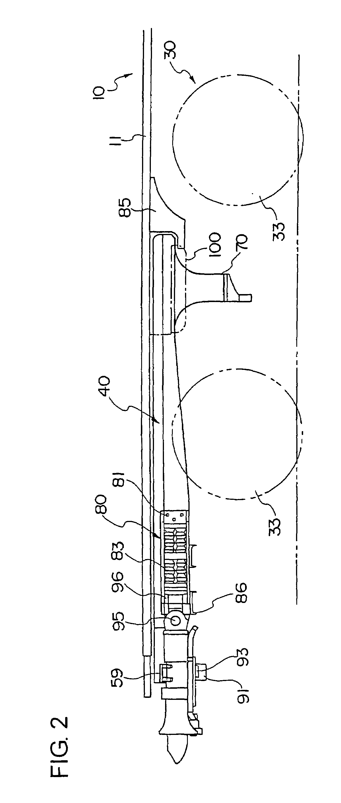
[0019]A car body 10 is mounted on a bogie 30 via a subframe 40 at the longitudinal end of the car body. In other words, a subframe 40 is disposed between the car body 10 and the bogie 30. The floor 11 of the car body 10 is formed by arranging long extruded hollow shape members made of aluminum alloy side by side in the width direction of the car body 10 with the length of the members extending in the longitudinal direction of the car body 10, and welding the members together via welding or friction stir welding. The subframe 40 is also made of aluminum alloy.

[0020]The subframe 40 is formed of a rigid, thick board, and the inside of the subframe is hollow. The hollow interior of the subframe functions as an air reservoir for an air spring 100.

[0021]FIGS. 7 through 9 illustrate the structure and character...


PUM


Abstract

The railway car comprises a subframe 40 disposed below a floor of the car body with a clearance therebetween, and a bogie 30 disposed below the subframe 40 with a clearance therebetween, wherein car body 10 and subframe 40 are connected via a first center pin 50 protruding downward from car body 10 or via a first center pin 50 protruding upward from subframe 40 toward car body 10, and subframe 40 and bogie 30 are connected via a second center pin 70 protruding downward from the subframe 40. A two-step bumper 61 is disposed between the first center pin 50 and the corresponding adjacent member, and two-step bumper 61 is disposed on both sides of center pin 50 in the width direction of car body 10. Car body 10 swings in the width direction when the bogie passes a point. After passing the point, car body 10 returns to its original position by the force of two-step bumper 61.

Description

FIELD OF THE INVENTION[0001]The present invention relates to a passenger railway car.DESCRIPTION OF THE RELATED ART[0002]Patent reference document 1 discloses a passenger railway car (rolling stock) having a car body mounted on a bogie, the car body and the bogie being connected via a so-called center pin and connecting link disposed on the bogie. Furthermore, the car body is mounted via an air spring on the bogie. One car body is connected to an adjacent car body via a coupling device. Power is transmitted from the front car body via a coupling device to the following car body, and via another coupling device to the subsequent car body. The coupling device comprises a coupler, a coupling rod, and an elastic member disposed at the center of the coupling device in the traveling direction so as to absorb the shock in that direction. Moreover, this portion is disposed so as to be able to slide with respect to the car body in a vertical movement.[0003]Patent Document 1: Japanese Patent ...

Claims


Application Information

Patent Timeline
Patent Type & Authority Patents(United States)
IPC IPC(8): B61F5/02B61F5/18B61F5/20B61F5/22B61F5/24B61G11/00
CPCB61F5/20B61F5/24
Inventor SEBATA, MICHIOTAKAI, HIDEOMURAMOTO, TERUMICHI
Owner HITACHI LTD
Why Eureka
Try Eureka