High pressure flexible hose

a flexible hose and high pressure technology, applied in the direction of flexible pipes, pipes, mechanical equipment, etc., to achieve the effects of simple structure, high tensile strength, and uniform diameter

Inactive Publication Date: 2005-12-27
DYNAFLEX
View PDF12 Cites 25 Cited by
  • Summary
  • Abstract
  • Description
  • Claims
  • Application Information

AI Technical Summary

Benefits of technology

[0010]In accordance with an embodiment, a flexible, thermoplastic hose for high pressure and high velocity fluid flow is provided with a flexible braided layer having a static electric drain therein. This is achieved, preferably, by having at least one textile yarn with electrically conductive fibers therein and braiding the conductive yarn with non-conductive textile yarns to form a high tensile strength layer which also provides a static electricity drain for the hose. The use of the electrically conductive yarn allows a more uniform diameter for the hose than prior art hoses having an electrically conductive tape between layers that results in a bump or enlargement in diameter at the location of the tape. The use of electrically conductive and non-conductive yarns in the braided layer results in a simpler, lighter weight and less expensive hose construction than the prior art construction that has an electrically conductive tube sandwiched between braided layers to conduct static electricity.

Problems solved by technology

The high velocity flow of fluids through the hose may create static electricity that could result in static sparking, which may cause fire or explosion, if the hose and equipment are not properly grounded.
The conductive tape results in a bump or enlargement in the circular cross-section of the hose which provides difficulty when crimping the hose to a metal fitting at an end to conduct the static electricity to ground.

Method used


Image

  • High pressure flexible hose
  • High pressure flexible hose

Examples


Embodiment Construction

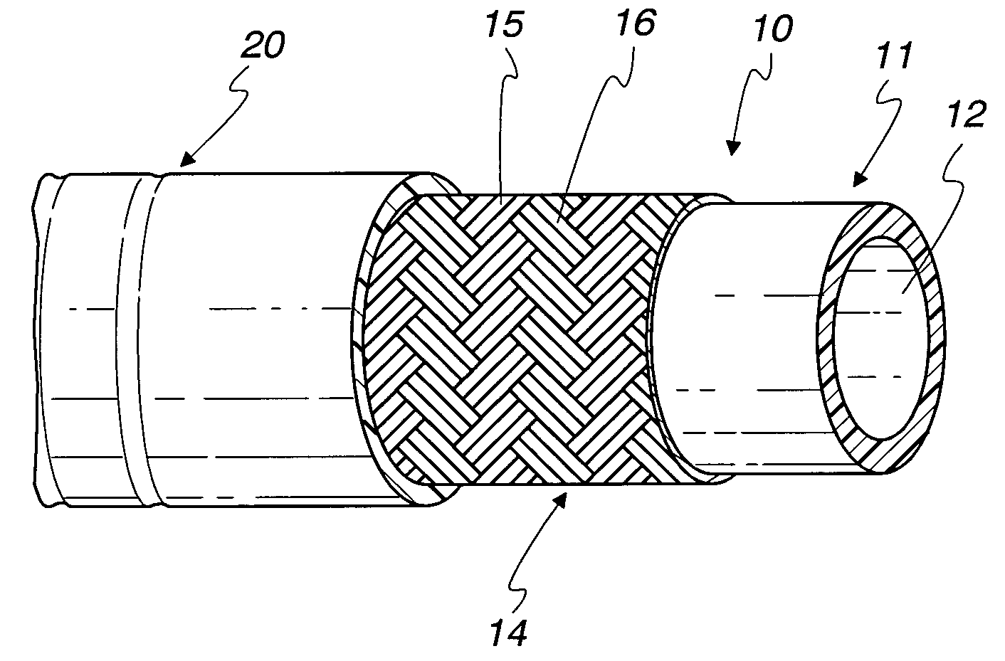
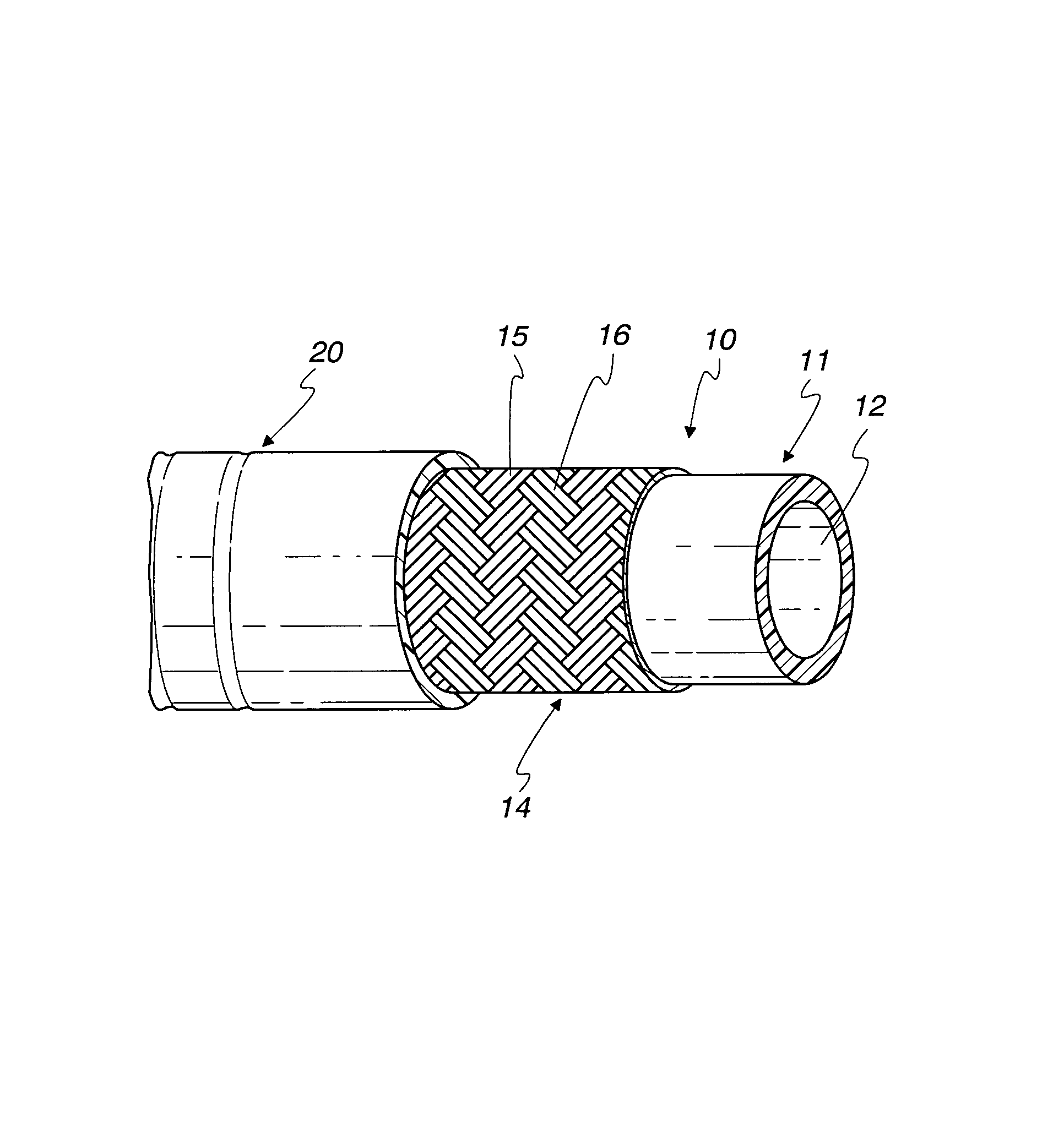
[0014]As shown in the drawings for purposes of illustration, a flexible thermoplastic hose 10 is provided an inner tube 11 having a hollow interior bore 12 through which the high velocity and high velocity fluid, such as paint, will flow. The preferred tube 11 is seamless, thermoplastic tube which is typically made of nylon or is nylon lined.

[0015]A high tensile strength reinforcement for the inner tube 11 is provided by one or more braided layers 14 which are formed of braided textile yarns 15 and 16. An outer cover or tube 20 made of abrasion resistant plastic such as polyurethane covers the braided layer to provide flexibility while allowing tight bends of the hose.

[0016]In accordance with the preferred embodiment, the braided reinforcement layer 14 is formed with one or more electrically conducting textile yarns 15 which are woven with non-electrically conducting yarns 16 to provide a static drain within the braided reinforcement layer.

[0017]The preferred electrically conducting...


PUM


Abstract

A flexible, thermoplastic hose for high pressure and high velocity flow is provided with a flexible braided reinforcement layer with a static drain therein for conducting static electricity towards a ground. This is achieved by having at least one textile fiber yarn with conductive fibers therein braided with non-conducting textile yarns to form the braided reinforcement layer. The preferred conducting fiber yarn is formed with metal fibers as well as plastic fibers. A method of manufacture of the hose comprises providing electrical conducting yarns and non-conducting yarns in a braiding machine and braiding them about a tube having a hollow bore through which fluid flows. An abrasion resistant outer cover layer of polyurethane is extruded over the braided layer having the drain therein. For higher pressure applications, a second braided reinforcement layer may also be provided over the inner braided layer having the electrically conductive yarns. Several conductive yarns may be used to have spaced electrically conductive yarns, e.g., at 3:00, 6:00, 9:00 and 12:00 in a circular cross-section through the hose.

Description

CROSS-REFERENCE TO RELATED APPLICATION[0001]This application claims the benefit of U.S. Provisional Patent Application No. 60 / 493,705, filed Aug. 8, 2003.FIELD OF THE INVENTION[0002]This invention relates to a flexible, high pressure, thermoplastic hose having a static electricity drain and used for various applications such as conveying paints, fuels, oils and solvents.BACKGROUND OF THE INVENTION[0003]These flexible thermoplastic hoses typically have internal bore diameters from ⅛ to ⅝ inch and a length of up to 500 feet. The working pressures in these hoses may be as high, e.g., 1,000 to 10,000 psi working pressures, and the hoses are desired to be light in weight, durable, flexible, abrasion resistant, and have a static discharge.[0004]The high velocity flow of fluids through the hose may create static electricity that could result in static sparking, which may cause fire or explosion, if the hose and equipment are not properly grounded. These hoses are provided with static elect...

Claims


Application Information

Patent Timeline
Patent Type & Authority Patents(United States)
IPC IPC(8): F16L11/08F16L11/127
CPCF16L11/085F16L11/127
Inventor D'AMICO, JAMES J.
Owner DYNAFLEX
Why Eureka
Try Eureka