
LED inspection lamp

a technology of led source and inspection lamp, which is applied in the field of inspection lamps, can solve the problems of affecting the detection of leakage, reducing the size of the lamp, and reducing the service life of the lamp,

Inactive Publication Date: 2005-12-27
R J DORAN +1
View PDF46 Cites 90 Cited by
  • Summary
  • Abstract
  • Description
  • Claims
  • Application Information

AI Technical Summary

Benefits of technology

"The invention is an inspection lamp that uses light emitting diodes (LEDs) to produce visible fluorescence of fluorescent materials. The LEDs have non-identical wavelengths, which means that some LEDs produce wavelengths that are more favorable for causing fluorescence than others. The inspection lamp may have one or more lenses to collimate the radiation produced by the LEDs. The LEDs may be arranged in a specific pattern to cause visible fluorescence of different fluorescent materials. The inspection lamp may have a handle and may be powered by an external power source or a rechargeable battery. The invention also provides a module with multiple LEDs that produce different wavelengths suitable for exciting fluorescent materials. The LEDs may be arranged in a specific pattern to cause visible fluorescence of different fluorescent materials. The inspection lamp may have a lens assembly with curved surfaces to produce beams of radiation that illuminate a specific area."

Problems solved by technology

The invisibility of leaked fluid can impair detection of the leak.
For some situations this defeats the purpose of the LED source as additional power must be consumed and the size of the lamp is increased accordingly.
However, traditional lamps suffer from a number of drawbacks.
Radiation absorbed or reflected by filters results in heat, often necessitating means to dissipate this heat.
Such inspection lamps have their own disadvantages such as the cost of the special discharge light sources having sufficient intensity, the added cost of electrical components required for operation of such light sources, a requirement for some such light sources to spend time wanning up to a required elevated operating temperature in order to properly function, and the tendency of many discharge light sources to specialize in production of wavelengths not effectively utilized by all popular fluorescent dyes.

Method used


Image

  • LED inspection lamp
  • LED inspection lamp
  • LED inspection lamp

Examples


Embodiment Construction

[0054]In this description, the term “LED source” is used. Unless the context requires otherwise, an “LED source” encompasses a single LED or a plurality of LEDs. LEDs include superluminescent diodes or laser diodes as well as conventional and other light emitting diodes. Laser diodes used in inspection lamps may be operated in a laser mode or a in a non-laser mode.

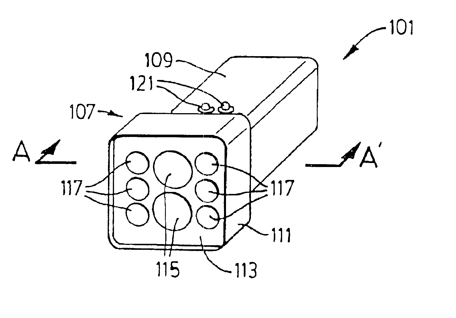
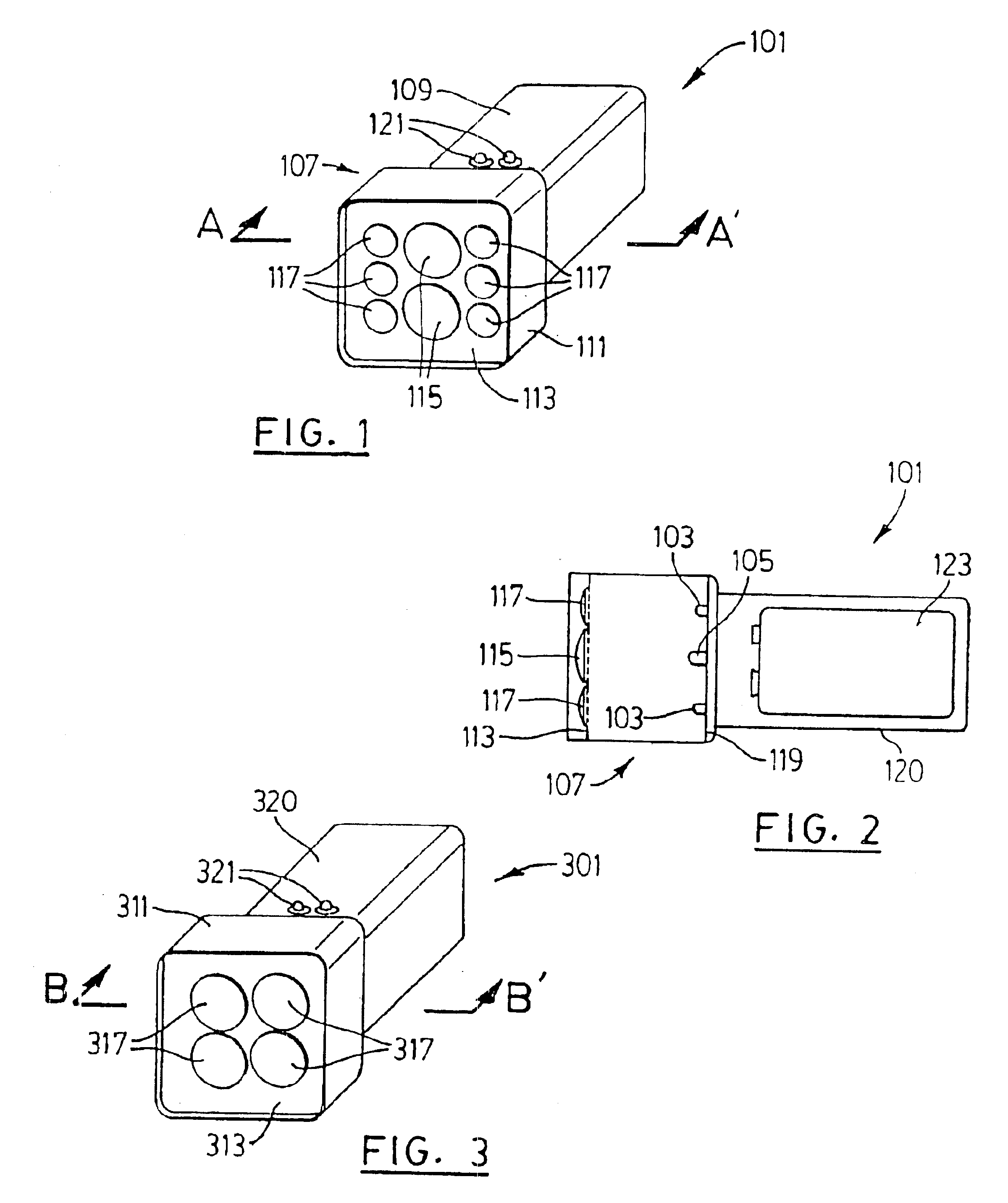
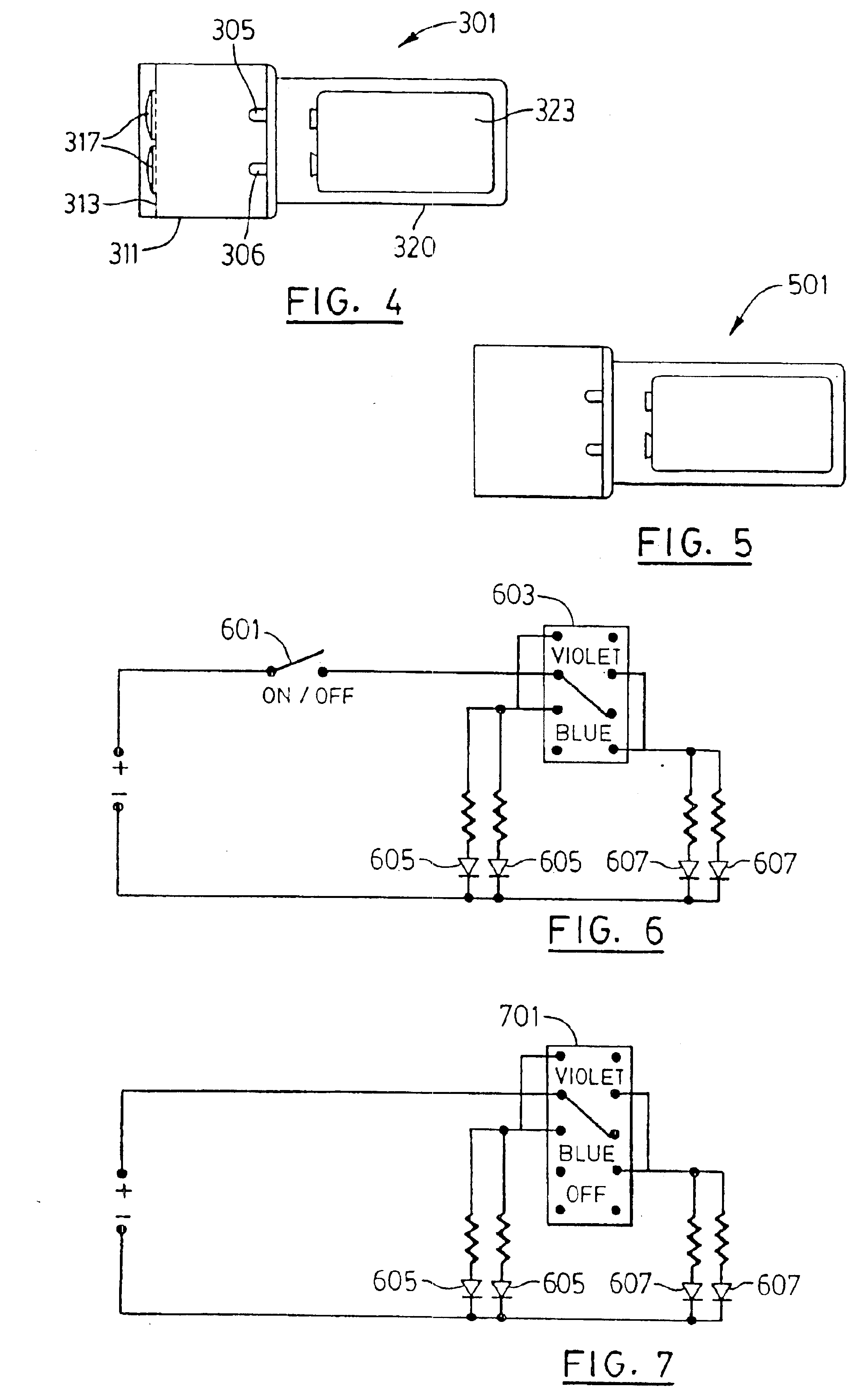
[0055]Also, numerous variants are described. Again, unless the context requires otherwise, such variants apply equally to all of the alternative embodiments described herein. Referring to FIG. 1 and FIG. 2 an inspection lamp 101 has six light emitting diodes 103 that produce ultraviolet radiation and two light emitting diodes 105 that produce blue visible light. The diodes are placed in a configuration similar to the lenses—later introduced as 115, 117—except as otherwise set out herein. The ultraviolet light emitting diodes 103 are of a currently available type having a peak emission wavelength of 370 nanometers with a na...


PUM

PropertyMeasurementUnit
voltageaaaaaaaaaa
voltageaaaaaaaaaa
voltageaaaaaaaaaa

Abstract

An LED inspection lamp has plurality of LED sources for emitting electromagnetic radiation at different peak wavelengths for causing visible fluorescence in different leak detection dyes. A lens is associated with each LED. Radiation passing through lenses is superimposed in target area at target distance. Another LED inspection lamp has plurality of LEDs emitting electromagnetic radiation at a peak wavelength. A lens adaptor has lens housing for attachment to LED inspection lamp with a single LED for causing visible fluorescence, and a lens. Substantially all of the radiation from the LED passes through the lens and is focused in a target area at a target distance from the lenses. LED spot lights have a similar configuration.

Description

FIELD OF THE INVENTION[0001]This invention is related to the general field of inspection lamps for detection of fluorescent materials, and in particular to the field of inspection lamps having light emitting diodes which produce radiation suitable for exciting the fluorescent materials to be detected by such lamps.BACKGROUND OF THE INVENTION[0002]Detection of leaks in systems containing fluids under pressure is often accomplished by causing visible fluorescence of fluorescent dyes that are added to the fluid in the system. Such systems may be, for example, refrigeration systems where the fluid under pressure is a refrigerant and leakage results in the fluid becoming an invisible gas upon escape. The invisibility of leaked fluid can impair detection of the leak. Addition of a fluorescent dye to the refrigerant allows easier detection of leaks by illuminating possible leakage points with radiation that causes the fluorescent dye to visibly fluoresce at the site of the leak.[0003]Leak ...

Claims


Application Information

Patent Timeline
Patent Type & Authority Patents(United States)
IPC IPC(8): G01N21/88G01N21/91
CPCG01N21/6447G01N21/8803G01N2201/062G01N2201/0627Y10S362/804
Inventor BRASS, JACKDORAN, RICHARD J.KLIPSTEIN, DONALD L.LEMONS, THOMAS M.
Owner R J DORAN
Learn More