Rod-guided crosshead assembly

a crosshead and rod-guide technology, applied in the direction of crossheads, bearing components, shafts and bearings, etc., can solve the problems of uneven wear, poor service life, and difficult lubrication of guides, so as to prevent wobbling over time, improve service life, and minimize guide wear

Inactive Publication Date: 2005-12-27
GARDNER DENVER INC
View PDF13 Cites 8 Cited by
  • Summary
  • Abstract
  • Description
  • Claims
  • Application Information

AI Technical Summary

Benefits of technology

[0003]In light of the problems associated with the known crossheads, it is a principal object of the invention to provide a crosshead assembly that is supplied with lubricant under pressure to minimize guide wear and that is strongly supported at its top and bottom to maintain crosshead alignment and prevent wobbling over time. Such an assembly, it is believed, offers a greater service life than any known crossheads and reduces the operating cost of the machine into which the assembly is installed.
[0004]It is another object of the invention to provide a crosshead assembly of the type described that is easier and less costly to install than conventional crossheads. Installation work can be undertaken with conventional tools and with minimal instruction.
[0005]It is an object of the invention to provide improved elements and arrangements thereof in a crosshead assembly for the purposes described which is lightweight in construction, inexpensive to manufacture, and dependable in use.

Problems solved by technology

These guides have always been difficult to lubricate and have tended to wear unevenly, imparting a wobbling motion to a crosshead as it moves.
Unfortunately, in cases where a crosshead is connected to a piston as in a pump, crosshead wobble has been found to break down the packing surrounding the piston and cause the pump to leak.
Leaks of this sort often require costly and time-consuming repairs made worse by the lost value of the broken machine's output during the repair period.

Method used


Image

  • Rod-guided crosshead assembly
  • Rod-guided crosshead assembly
  • Rod-guided crosshead assembly

Examples


Embodiment Construction

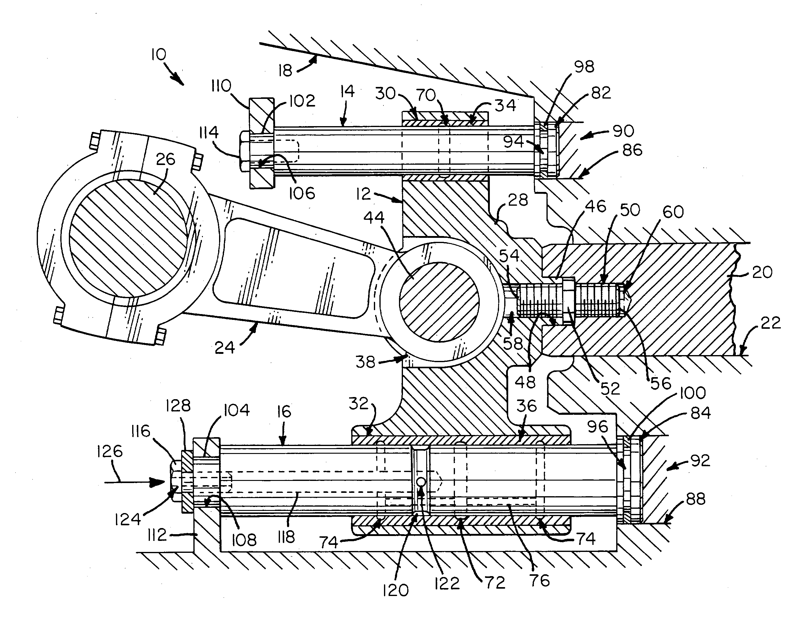
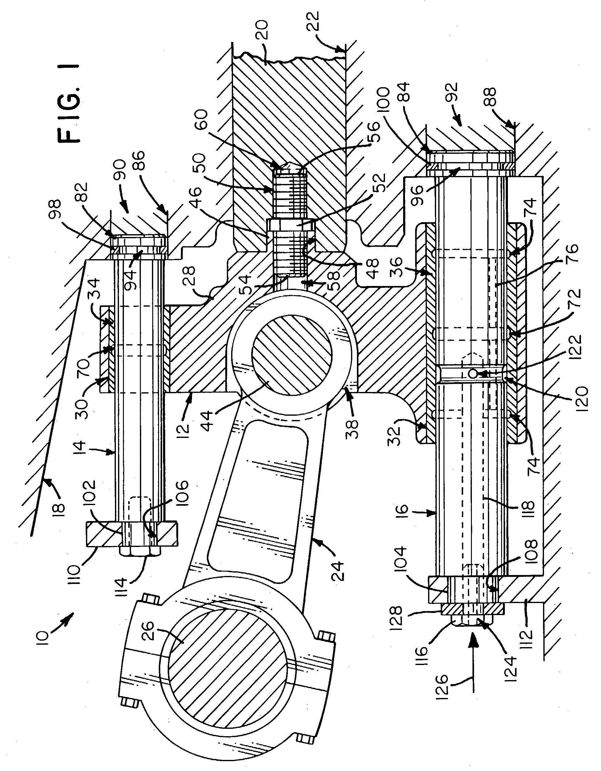
[0012]Referring now to the FIGS., a rod-guided crosshead assembly in accordance with the present invention is shown at 10. Assembly 10 includes a crosshead 12 slidably mounted on a pair of guide rods 14 and 16 affixed within a pump 18. A piston 20 is connected to the front of crosshead 12 and is snugly fitted in a bore 22 in pump 18 adjacent rods 14 and 16. A crank arm 24 extends from the rear of crosshead 12 and is connected to the drive shaft 26 of pump 18. In use, crosshead 12 converts the rotary motion of crank arm 24 into linear motion such that piston 20 is reciprocated in bore 22 to pressurize a fluid located in bore 22.

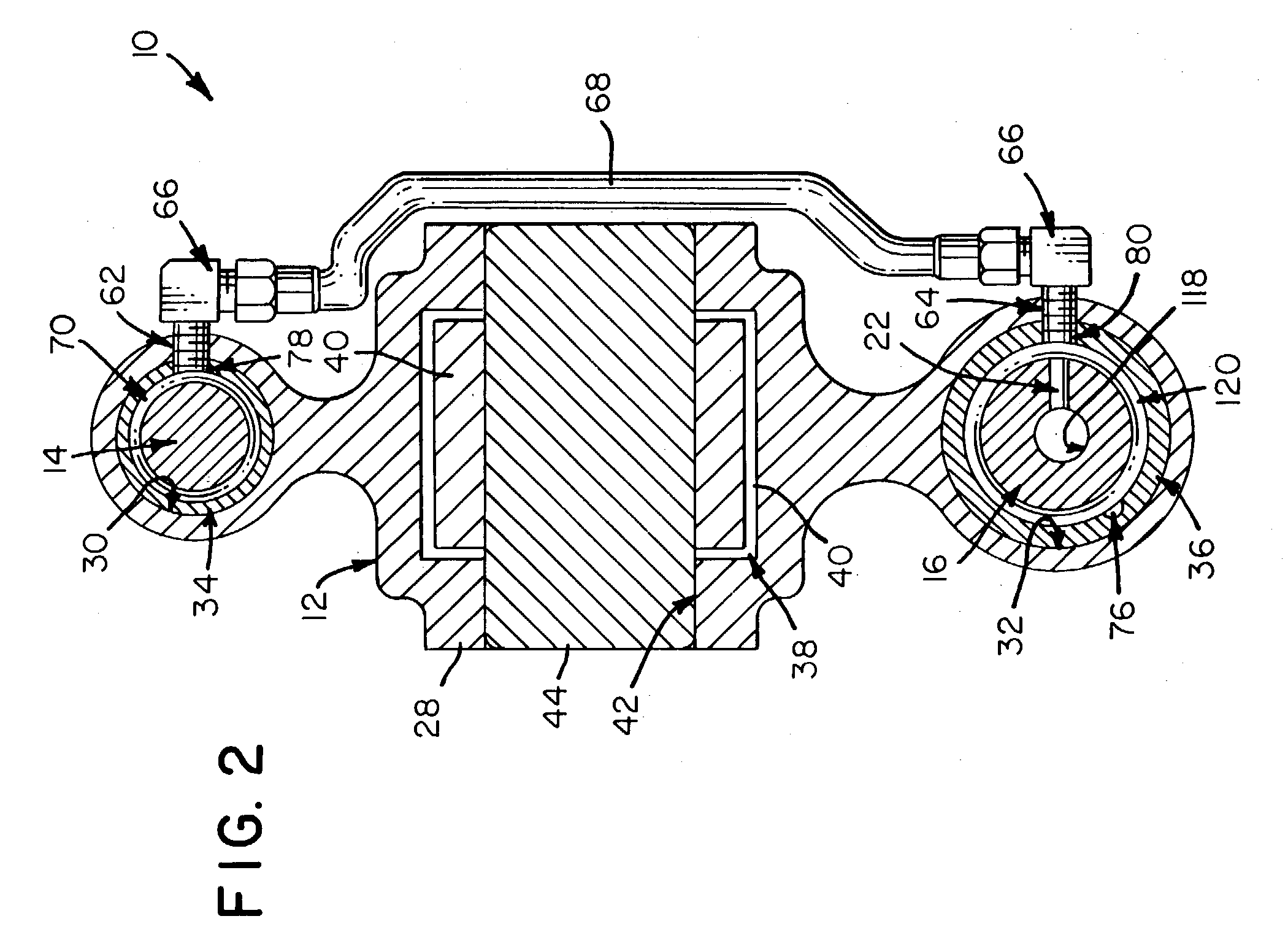
[0013]Crosshead 12 includes an elongated body 28 having parallel passageways 30 and 32 at its top and bottom. Passageways 30 and 32 open toward the front and rear of body 28 and carry tubular bushings 34 and 36. Located between passageways 34 and 36 is a cavity 38 that opens toward the rear of body 28 and receives the ring-shaped link 40 at one end of crank ar...


PUM


Abstract

A rod-guided crosshead assembly for use in a pump or similar machine. The assembly includes a crosshead having a rigid body with a pair of parallel passageways passing from the front to the rear of the body. The body also has a rearwardly opening cavity between the parallel passageways for receiving the ring-shaped link of a crank arm. Further, the body has a transverse aperture intersecting the cavity for receiving a pivot pin capable of passing through the ring-shaped link to pivotally connect the crank arm to the crosshead. The body additionally has a connecting rod extending from the front thereof for connecting to a reciprocating machine part. A conduit connects the parallel passageways and places them in fluid communication with one another. A pair of parallel guide rods extends through the parallel passageways. One of the guide rods is hollow so as to define an elongated aperture therein and has a peripheral groove around its exterior surface. A transverse passageway connects the peripheral groove and the elongated aperture. A pressurized oil source is in fluid communication with the elongated aperture so that oil supplied thereto travels to the parallel passageways to lubricate the crosshead as it moves on the guide rods.

Description

FIELD OF THE INVENTION[0001]The present invention relates generally to bearings and, more particularly, linear bearings for crossheads.BACKGROUND OF THE INVENTION[0002]Crossheads have long been used in motors, pumps, compressors and other machines to smoothly convert rotational motion into linear motion. As is well known, conventional crossheads slide linearly between a pair of cupped guides at their tops and bottoms. These guides have always been difficult to lubricate and have tended to wear unevenly, imparting a wobbling motion to a crosshead as it moves. Unfortunately, in cases where a crosshead is connected to a piston as in a pump, crosshead wobble has been found to break down the packing surrounding the piston and cause the pump to leak. Leaks of this sort often require costly and time-consuming repairs made worse by the lost value of the broken machine's output during the repair period.SUMMARY OF THE INVENTION[0003]In light of the problems associated with the known crosshead...

Claims


Application Information

Patent Timeline
Patent Type & Authority Patents(United States)
IPC IPC(8): F16C5/00F16C33/10
CPCF16C5/00F16C33/1085
Inventor VICARS, BERTON L.
Owner GARDNER DENVER INC
Why Eureka
Try Eureka