
System for indirectly ablating tissue using implanted electrode devices

a technology of indirect ablation and electrode device, which is applied in the direction of prosthesis, application, therapy, etc., can solve the problems of increasing treatment duration, requiring significant skill for meticulous precision of multiple electrode placement, and often difficult accurate processing

Inactive Publication Date: 2005-12-27
BOSTON SCI SCIMED INC
View PDF12 Cites 16 Cited by
  • Summary
  • Abstract
  • Description
  • Claims
  • Application Information

AI Technical Summary

Benefits of technology

The present invention relates to medical probe assemblies and methods for ablating tissue. The invention contemplates the use of multiple electrode arrays that can be implanted into tissue and ablated with a separate electrode device. The electrode arrays can be detachably coupled to a delivery device, which can be a cannula or other elongated tubular member. The delivery device can include one or more distally located electrodes that can be directly or indirectly exposed to radio frequency (RF) energy to ablate the tissue. The use of multiple electrode arrays provides a greater region for ablation and also creates a roadmap for tracking the progress of managing the ablated tissue during future follow-ups. The invention also contemplates the use of a separate RF energy source that can be introduced into the tissue to ablate it.

Problems solved by technology

Because of the echogenic cloud created by the ablated tissue, however, this process often becomes difficult to accurately perform.
This considerably increases treatment duration and requires significant skill for meticulous precision of multiple electrode placement.

Method used


Image

  • System for indirectly ablating tissue using implanted electrode devices
  • System for indirectly ablating tissue using implanted electrode devices
  • System for indirectly ablating tissue using implanted electrode devices

Examples


Embodiment Construction

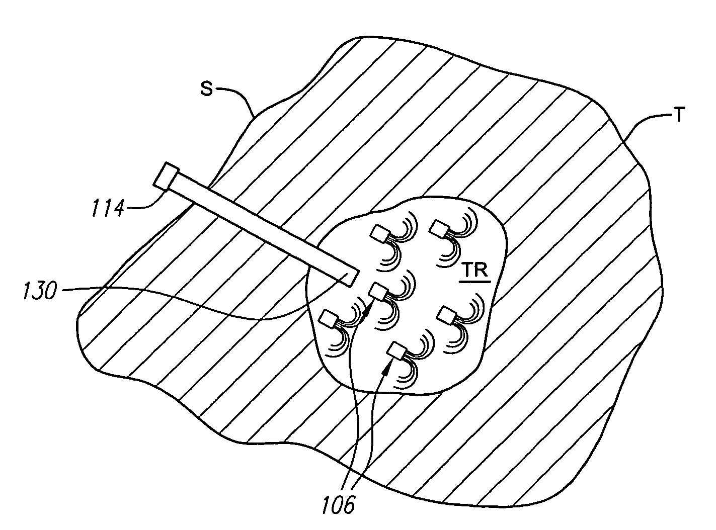
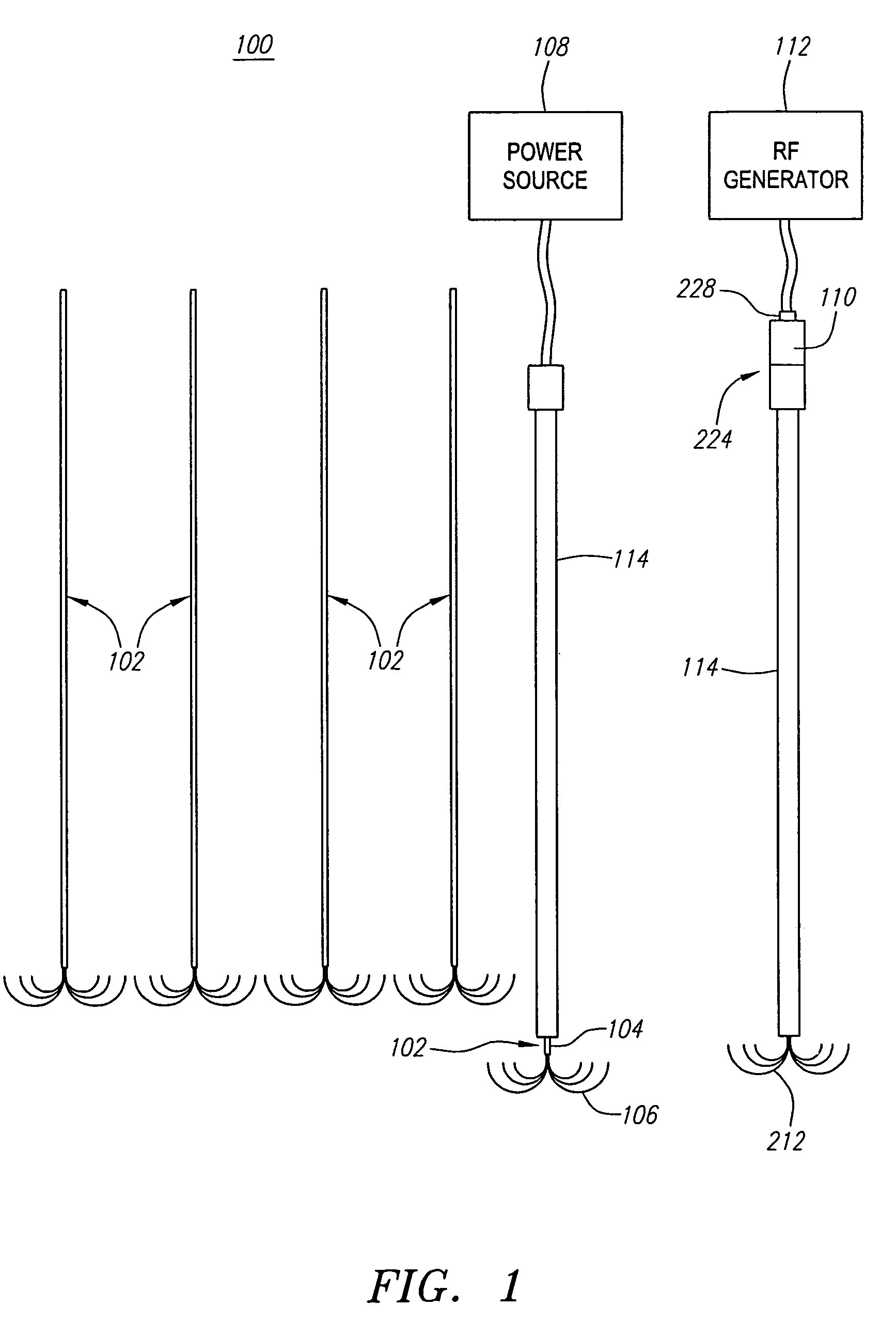
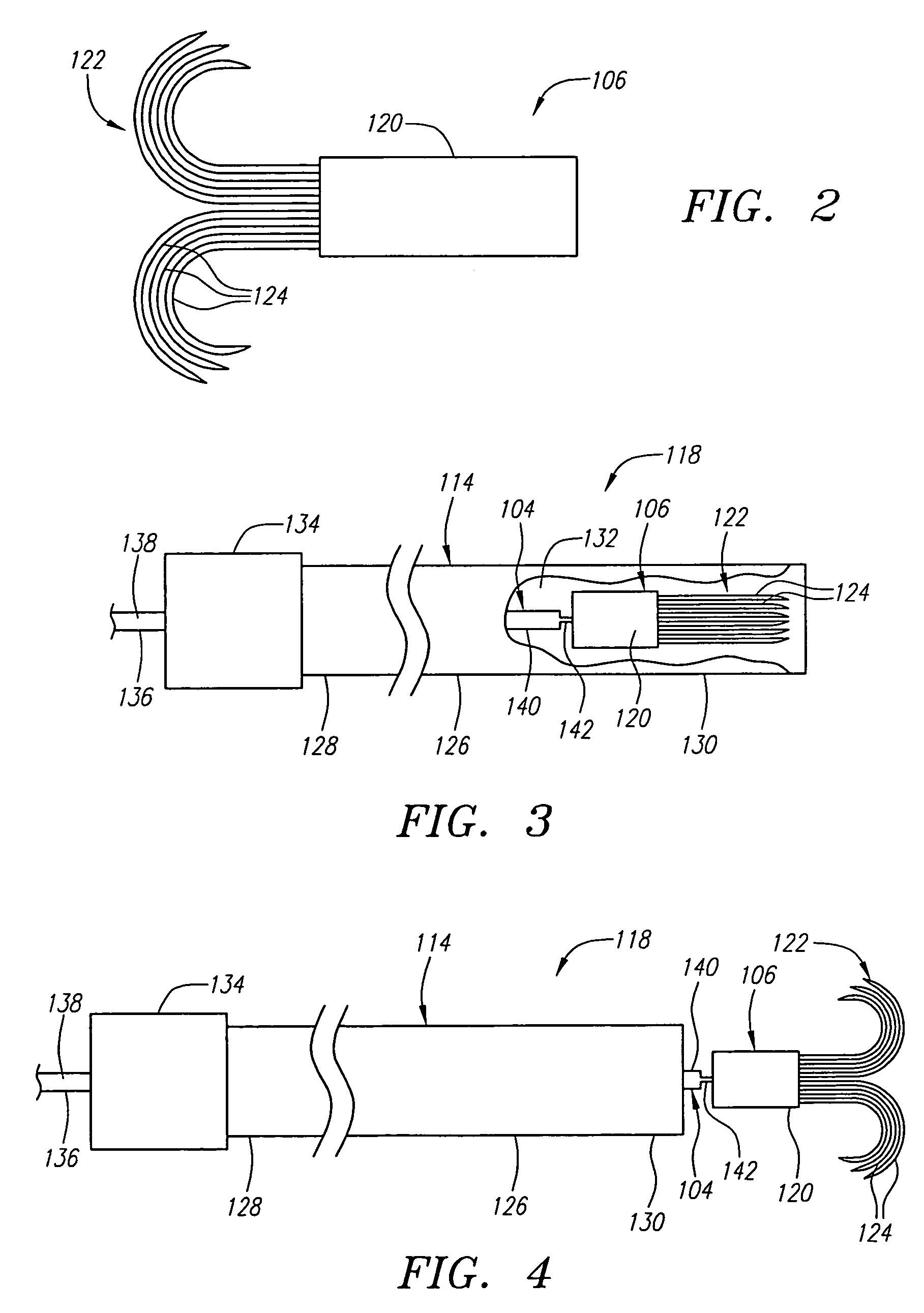
[0027]FIG. 1 illustrates a tissue ablation system 100 constructed in accordance with a preferred embodiment of the present inventions. The tissue ablation system 100 generally comprises a plurality of self-delivering single electrode assemblies 102, each of which includes a delivery device 104 and a distally mounted electrode device 106. Each of the delivery devices 104 is configured for detaching from, and implanting, the associated electrode device 106 within tissue. The tissue ablation system 100 further comprises a power source 108 that is configured for conveying electrical current through each of the single electrode assemblies 102 to detach the corresponding electrode device 106 from the delivery device 102 in a controlled manner. The tissue ablation system 100 further comprises an elongated cannula 114 configured for delivering the single electrode assemblies 102 to the tissue.

[0028]Thus, it can be appreciated that the delivery devices 104 can be exchanged within the cannula...


PUM


Abstract

Systems and methods are provided for ablating tissue by implanting a plurality of electrode devices within the tissue to be treated and exposing the implanted electrode devices with RF energy conveyed from a separate electrode device. In this manner, a greater region of tissue is ablated than what would normally be ablated with the separate electrode device. In addition, the implanted electrode devices can create a roadmap that allows the progress of the treatment to be managed during follow-ups. The implanted electrode devices can be variously delivered to the tissue, for example, by detaching the electrode devices from one or more delivery devices. For example, a core wire with an electrolytically detachable junction can be used to separate the electrode device from the core wire. Pusher rods with mechanically detachable junctions are also contemplated.

Description

FIELD OF THE INVENTION[0001]The field of the invention relates generally to the structure and use of radio frequency (RF) electrosurgical probes for the treatment of solid tissue, and more particularly, to electrosurgical probes having multiple tissue-penetrating electrodes that are deployed in an array to treat large volumes of tissue.BACKGROUND OF THE INVENTION[0002]The delivery of radio frequency (RF) energy to target regions within solid tissue is known for a variety of purposes of particular interest to the present inventions. In one particular application, RF energy may be delivered to diseased regions (e.g., tumors) in target tissue for the purpose of tissue necrosis. RF ablation of tumors is currently performed within one of two core technologies.[0003]The first technology uses a single needle electrode, which when attached to a RF generator, emits RF energy from the exposed, uninsulated portion of the electrode. This energy translates into ion agitation, which is converted ...

Claims


Application Information

Patent Timeline
Patent Type & Authority Patents(United States)
IPC IPC(8): A61B18/14A61B19/00A61N1/06
CPCA61B18/1477A61N1/06A61B19/54A61B2018/143A61B2018/1432A61B2018/1495A61B2019/5487A61B90/39A61B2090/3987
Inventor KELLY, AMY C.GARABEDIAN, ROBERT J.LANDREVILLE, STEVEN K.
Owner BOSTON SCI SCIMED INC
Learn More