Efficiency optimization control for permanent magnet motor drive

a permanent magnet motor and optimization control technology, applied in the direction of motor/generator/converter stopper, dynamo-electric gear control, dynamo-electric converter control, etc., can solve problems such as rotor angle estimation errors, and achieve the effect of improving efficiency and improving motor efficiency

Inactive Publication Date: 2005-12-27
INFINEON TECH AMERICAS CORP
View PDF13 Cites 29 Cited by
  • Summary
  • Abstract
  • Description
  • Claims
  • Application Information

AI Technical Summary

Problems solved by technology

Rotor angle estimation errors may be due to inaccuracies in estimator (angle) parameters or in motor back emf feedback sensing.

Method used


Image

  • Efficiency optimization control for permanent magnet motor drive
  • Efficiency optimization control for permanent magnet motor drive
  • Efficiency optimization control for permanent magnet motor drive

Examples


Embodiment Construction

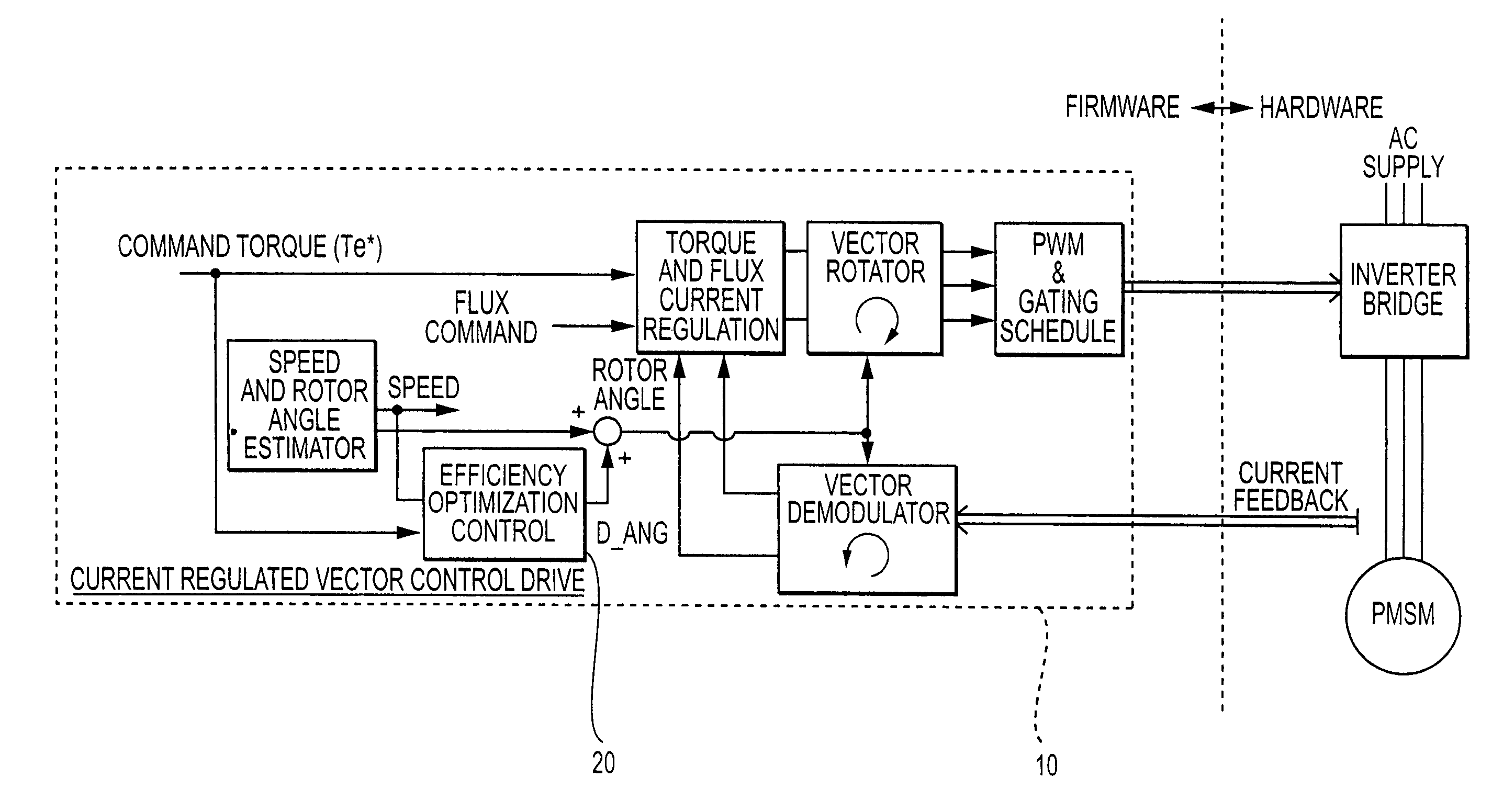
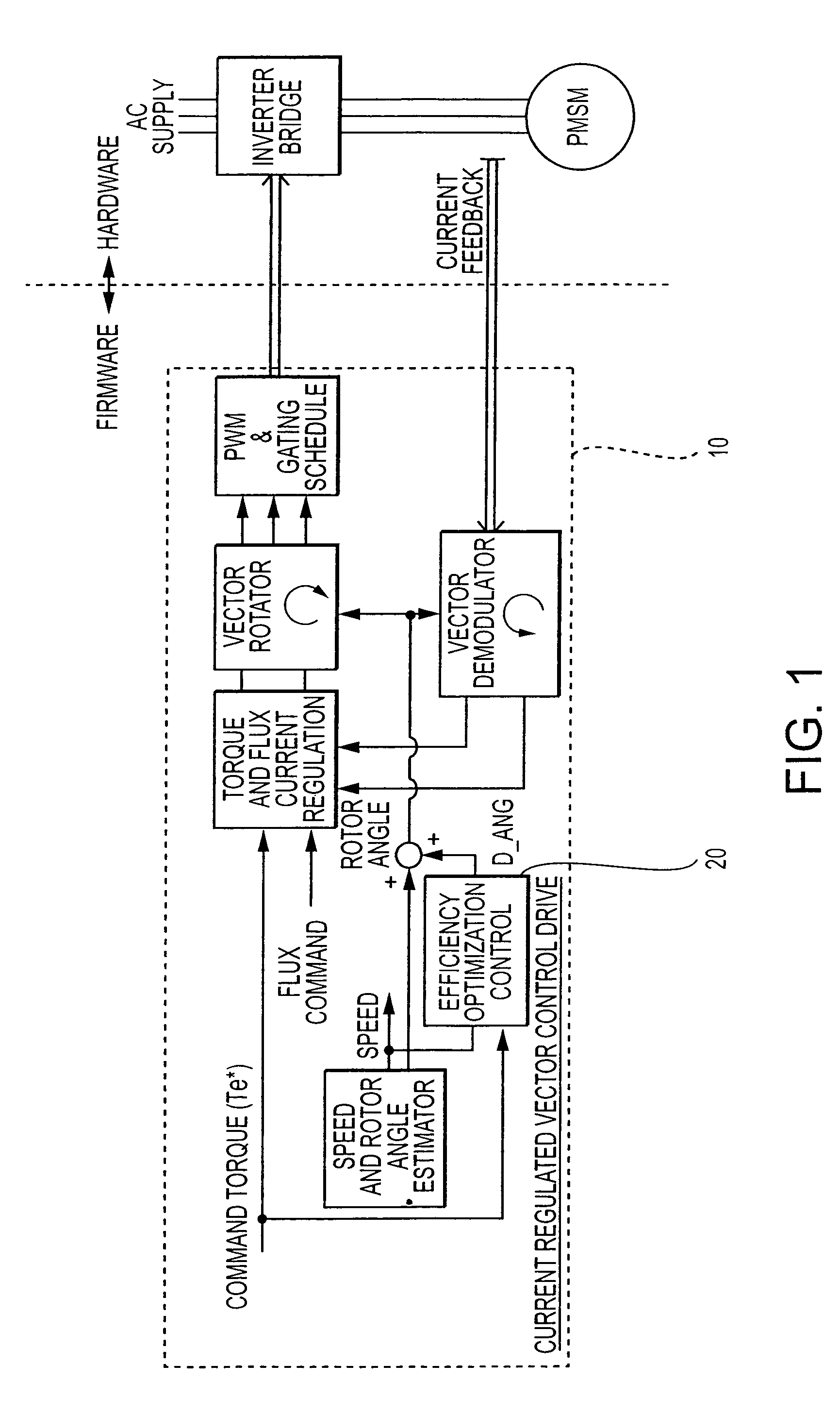
[0017]FIG. 1 is a block diagram illustrating the placement of the efficiency control algorithm module 20 in a vector controlled system 10.

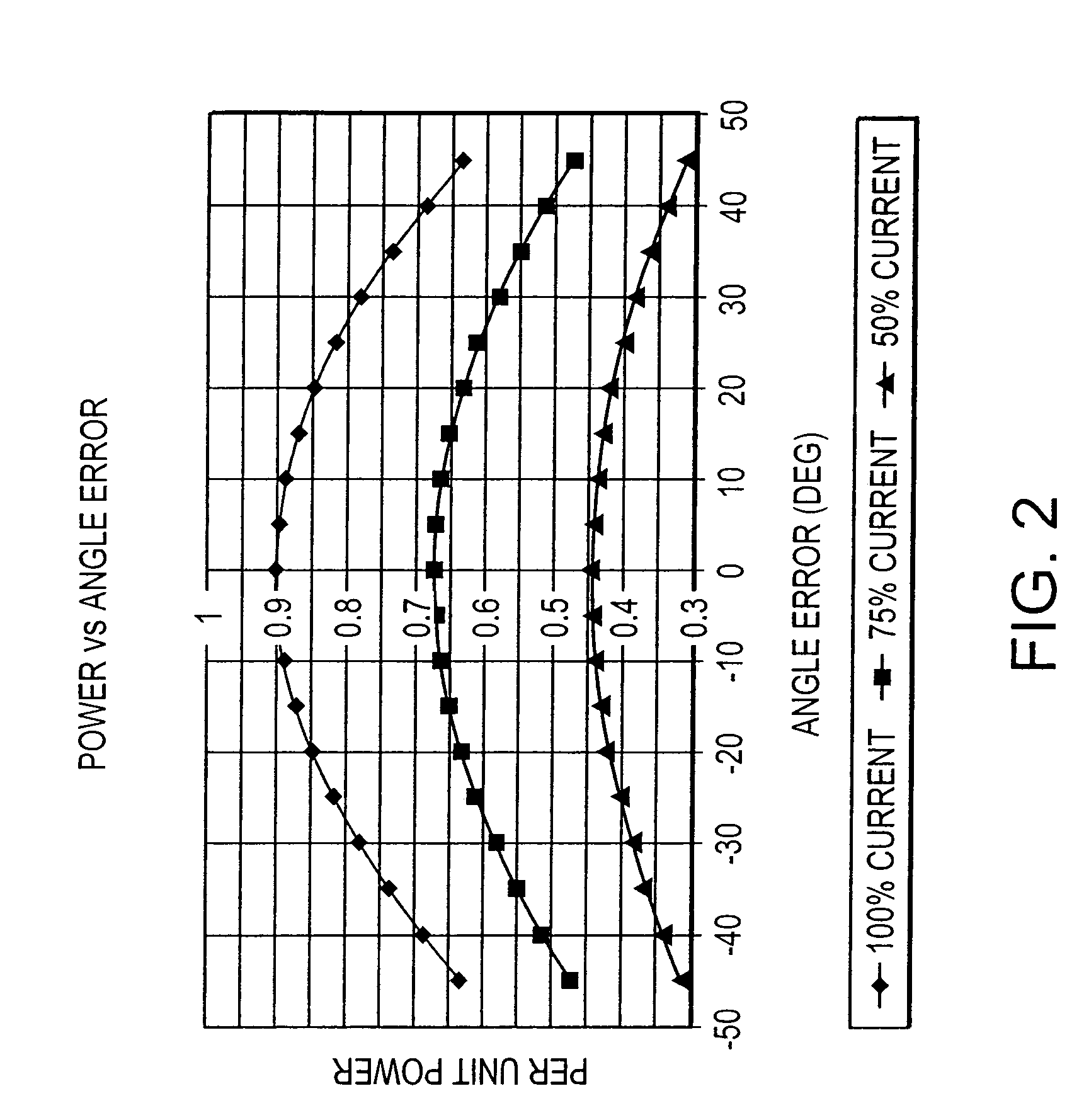
[0018]FIG. 3 shows the efficiency optimization control module in more detail. The efficiency optimization on / off control 25 monitors the drive run command, the estimated motor speed and the torque command. If (1) the run command is asserted, (2) speed variation (speed derivative) stays within certain bounds, and (3) motor current (torque command) is above a certain level then switch SW1 is activated. The output correction angle (D—Ang) is discharged (for example, in 10 sec) to zero if any of the above three conditions cannot be satisfied.

[0019]The torque difference block 30 computes a difference (between present and a past sample) in the average (for example, filtered 10 rad / sec) command torque. The search control block 35 determines the state of SW2 based on the sign of D—Trq. If the torque difference (D—Trq) is equal to or larger than zero then ...


PUM


Abstract

A method and system for modifying an estimated rotor angle for improved efficiency in a PMSM drive system. A module monitors a run command, a torque command, and an estimated speed; and in response thereto, generates an output correction angle for modifying the estimated rotor angle. The output correction angle may be added to the estimated rotor angle. The output correction angle may be generated only for predetermined conditions of said run command, torque command, and speed. In particular, the output correction angle may be generated (1) when the run command is asserted, (2) when the torque command is above a predetermined level, and (3) when variations in the speed are within predetermined limits.

Description

CROSS-REFERENCE[0001]This is a continuation of U.S. patent application Ser. No. 10 / 684,928, filed Oct. 14, 2003, entitled EFFICIENCY OPTIMIZATION CONTROL FOR PERMANENT MAGNET MOTOR DRIVE, now U.S. Pat. No. 6,856,109 B2. This application is based upon and claims priority of U.S. Provisional Application Ser. No. 60 / 418,735, filed Oct. 15, 2002, incorporated by reference.BACKGROUND OF THE INVENTION[0002]1. Field of the Invention[0003]The present invention relates to motor drives, and more particularly to a motor drive with improved rotor angle estimation for greater efficiency.[0004]2. Description of the Related Art[0005]Most low cost motor drive systems employ encoderless (sensorless) control techniques. The rotor angle is estimated based on a motor model or motor back emf sensing, for example. The motor efficiency and torque per ampere capability can be significantly reduced if an incorrect rotor angle is used for controlling a permanent magnet synchronous motor (PMSM). Rotor angle e...

Claims


Application Information

Patent Timeline
Patent Type & Authority Patents(United States)
IPC IPC(8): H02P21/00H02P21/08H02P21/14
CPCH02P21/0042H02P21/146H02P2207/05H02P21/26H02P21/18Y02P80/10
Inventor HO, EDDY YING YIN
Owner INFINEON TECH AMERICAS CORP
Why Eureka
Try Eureka