Circuit protection device with timed negative half-cycle self test

a circuit protection device and half-cycle self-test technology, applied in emergency protective circuit arrangements, testing circuits, instruments, etc., can solve problems such as ground fault, low power arc between the two conductors, and arc faul

Inactive Publication Date: 2005-12-27
PASS SEYMOUR
View PDF21 Cites 111 Cited by
  • Summary
  • Abstract
  • Description
  • Claims
  • Application Information

AI Technical Summary

Problems solved by technology

An arc fault may be caused by damaged insulation on the hot line conductor or neutral line conductor, or on both the hot line conductor and the neutral line conductor.
The damaged insulation may cause a low power arc between the two conductors and a fire may result.
On the other hand, a ground fault occurs when a current carrying (hot) conductor contacts ground to create an unintended current path.
The unintended current path represents an electrical shock hazard.
Further, because some of the current flowing in the circuit is diverted into the unintended current path, a differential current is created between the hot / neutral conductors.
As in the case of an arc fault, ground faults may also result in fire.
If the wiring insulation within a load circuit becomes damaged, the hot conductor may contact ground, creating a shock hazard for a user.
A ground fault may also occur when the equipment comes in contact with water.
A ground fault may also be caused by damaged insulation within the facility.
Circuit interruption is typically effected by opening the line between the source of power and the load.
Another type of ground fault may occur when the load neutral terminal, or a conductor connected to the load neutral terminal, becomes grounded.
This scenario represents a double-fault condition, i.e., when both the hot conductor and the load neutral conductor are grounded, the GFCI may fail to trip, causing a user to experience serious injury or death.
One drawback to this approach is that the circuitry is relatively expensive and increases the size of the GFCI circuitry.
Those of ordinary skill in the art will understand that a miswire condition of this type will result in a loss of GFCI protection at the duplex receptacles on the face of the GFCI.
One drawback to this approach is that the GFCI does not include a self-test of the electrical circuit.
Another drawback to this approach is that the visual display does not indicate a lock-out of load side power by the interrupting contacts.
In light of all of the approaches discussed above, there are many other types of failures, such as those involving the GFCI sensing circuitry, that require manual testing.
If the device fails to reset, the user understands that the device has failed and is in a lock-out condition.
This approach has drawbacks as well.
While regular testing is strongly encouraged by device manufacturers, in reality, few users test their GFCIs on a regular basis.

Method used


Image

  • Circuit protection device with timed negative half-cycle self test
  • Circuit protection device with timed negative half-cycle self test
  • Circuit protection device with timed negative half-cycle self test

Examples


second embodiment

[0061]As embodied herein and depicted in FIG. 11, a schematic of a circuit protection device 10 in accordance with the present invention is disclosed. This embodiment differs from the embodiments depicted in FIGS. 1–10 by the addition of control gate 1116, by-pass circuit 1126, and several alternative routes for the ring detector 400 output.

[0062]Control gate 1116 is coupled to detector 16 and configured to receive either detector output signal 1120 or filtered detector output signal 20. Control gate 1116 gates these signals and provides a gated and delayed detection signal to SCR 24 (SCR out). Control gate 1116 is configured to recycle between a test state and a non-test state. The durations of each of the two states are established by a timing circuit. Those of ordinary skill in the art will recognize that the timing circuit may be of any suitable type. For example, the timing circuit may be an external clocking arrangement driven by a local oscillator (not shown), a timer dispose...

third embodiment

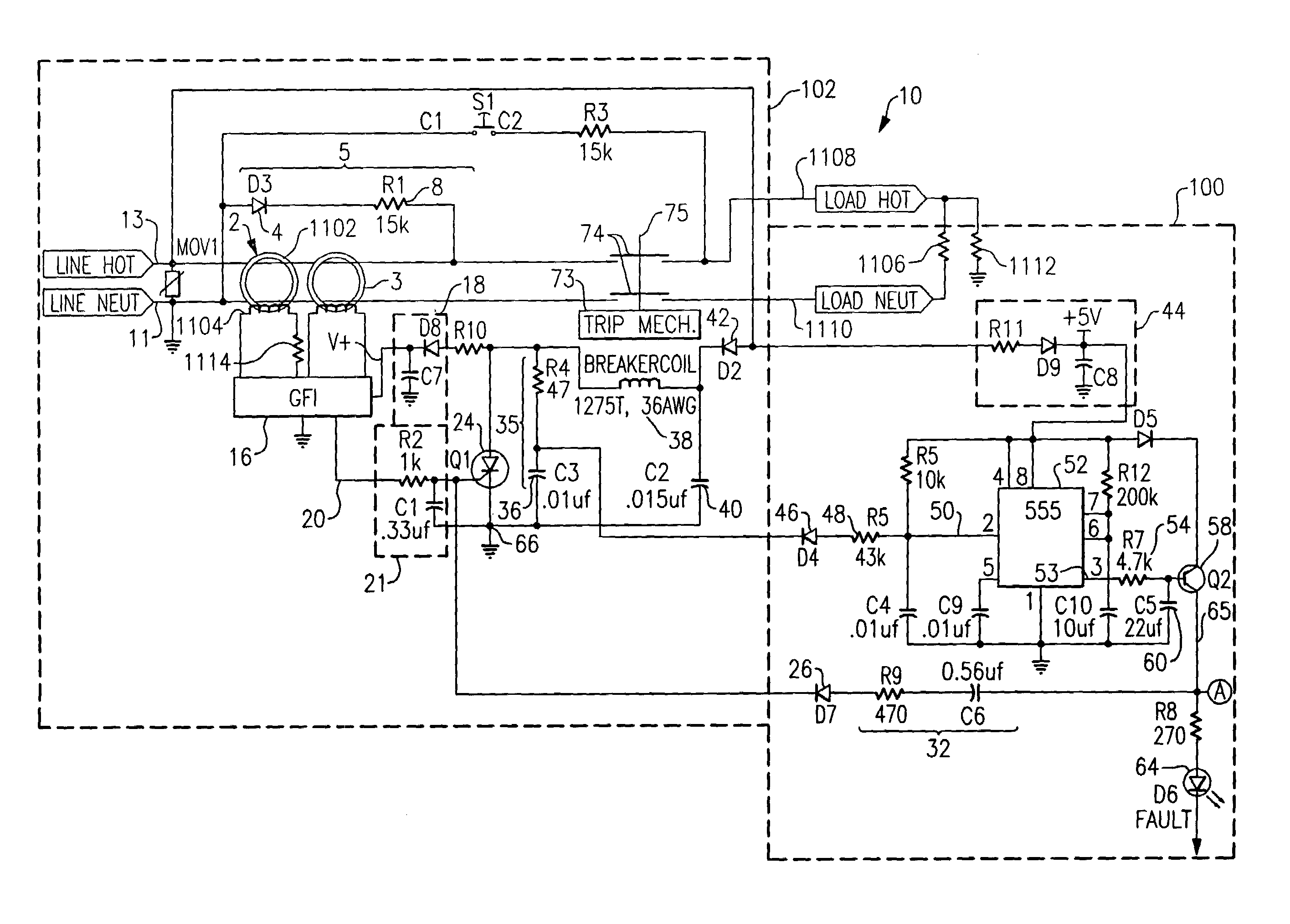
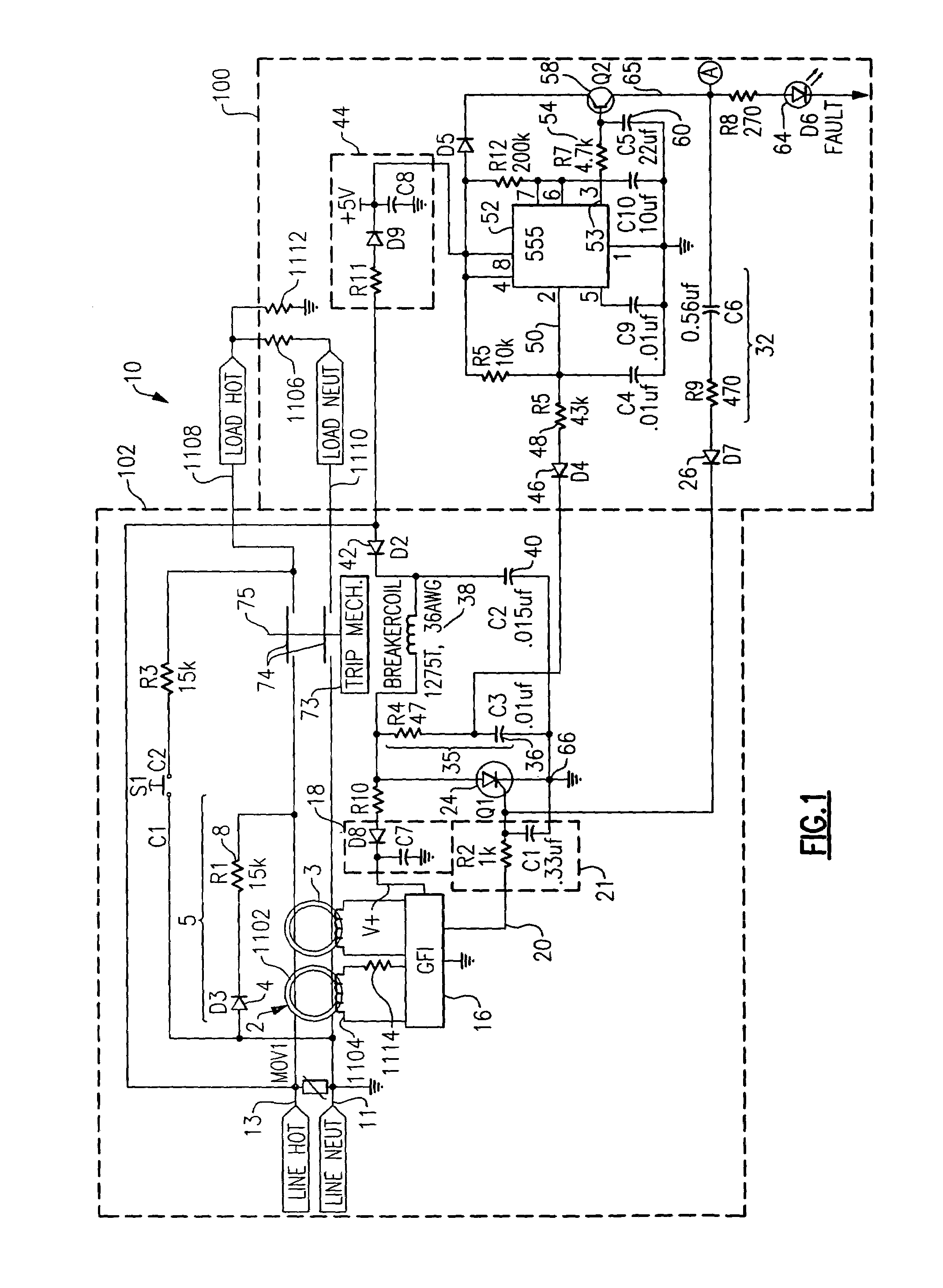
[0075]As embodied herein and depicted in FIG. 12, a schematic of a circuit protection device in accordance with the present invention is disclosed. FIG. 12 is a schematic diagram of an alternate embodiment in which the fault simulation circuit generates a simulated negative half cycle grounded neutral signal. Reference is made to U.S. patent application Ser. No. 10 / 768,530, which is incorporated herein by reference as though fully set forth in its entirety, for a more detailed explanation of the fault simulation signal. Note that test circuit 1128 does not include diode 4.

[0076]The GFI circuit 102 in FIG. 12 includes a transformer 2 that is configured to sense a load-side ground fault when there is a difference in current between the hot and neutral conductors. Transformer 2 sends sensed signal to detector circuit 16. GFI circuit 102 also includes a grounded neutral transmitter 3 that is configured to detect grounded neutral conditions. Those skilled in the art understand that the c...


PUM


Abstract

The present invention is directed to an electrical wiring protection device for use in coupling an AC power distribution system to at least one electrical load. The device includes an automated self-test circuit coupled to the AC power distribution system. The automated self-test circuit is configured to generate at least one simulated fault signal during a first predetermined half-cycle of AC power. A detector circuit is coupled to the automated self-test circuit. The detector circuit generates a detection signal in response to the at least one simulated fault signal. An interval timing circuit is coupled to the test circuit. The interval timing circuit is configured to enable the automated self-test circuit to generate the at least one simulated fault signal during a first predetermined interval and not enable the test circuit during a subsequent second predetermined interval. The first predetermined interval and the second predetermined interval are recurring time intervals.

Description

CROSS-REFERENCE TO RELATED APPLICATIONS[0001]This is a continuation-in-part of U.S. patent application Ser. No. 10 / 668,654 filed on Sep. 23, 2003, now U.S. Pat. No. 6,873,158, issued on Mar. 29, 2005 the content of which is relied upon and incorporated herein by reference in its entirety, and the benefit of priority under 35 U.S.C. § 120 is hereby claimed. U.S. patent application Ser. No. 10 / 668,654 claims priority under 35 U.S.C. §120 based on U.S. Pat. No. 6,674,289, which was filed on Nov. 29, 2000, the content of which is also relied upon and incorporated herein by reference in its entirety. U.S. Pat. No. 6,674,289 claims priority under 35 U.S.C. §119(e) based on U.S. Provisional Patent Application Ser. No. 60 / 183,273, filed Feb. 17, 2000, the contents of which are relied upon and incorporated herein by reference in their entirety.BACKGROUND OF THE INVENTION[0002]1. Field of the Invention[0003]The present invention relates generally to electric circuit protection devices, and pa...

Claims


Application Information

Patent Timeline
Patent Type & Authority Patents(United States)
IPC IPC(8): G01R31/14G01R31/327
CPCG01R31/14H02H3/335
Inventor FINLAY, SR., DAVID A.RICHARDS, JEFFREY C.
Owner PASS SEYMOUR
Why Eureka
Try Eureka