Trans-conductance amplification circuit, trans-conductance filter circuit, and filtering method

a filter circuit and transconductance technology, applied in the field of filter circuits, can solve the problems of transistor operating outside, method of varying cut-off frequencies, electronic appliances and their filter circuits, etc., and achieve the effects of avoiding output voltage amplitude reduction, reducing or eliminating, and exploiting noise resistan

Inactive Publication Date: 2005-12-27
FUJITSU LTD
View PDF5 Cites 15 Cited by
  • Summary
  • Abstract
  • Description
  • Claims
  • Application Information

AI Technical Summary

Benefits of technology

[0024]The following effects can be achieved by the trans-conductance amplification circuit and trans-conductance filter circuit of the present invention: (1) the cut-off frequency range can be broadened; (2) the output voltage amplitude reduction can be avoided; and (3) the advantages of differential circuit such as advanced power source variation and noise resistance can be exploited.
[0029]The output voltage amplitude reduction can be avoided by reducing or eliminating the need for stacked transistors.

Problems solved by technology

The wide frequency range requirement, in particular, has become more demanding for electronic appliances and their filter circuits.
These methods for varying cut-off frequencies, however, have problems.
An effort to vary the cut-off frequency, however, may result in the transistor operating outside this region.
Thus, at this operating condition, the constant current feature cannot be used for the transistor.
Consequently, it is impossible to provide normal actions of the gm circuit requiring a constant current source.
Consequently, the range of the cut-off frequency variation is also limited.
They are problematic, however, in that they reduce the output signal amplitude.
This amplitude reduction is a grave problem where minimizing the electric power consumptions of electronic circuits is a priority.
When the variable resistance value is large or becomes large, however, the differential circuit function becomes lost, and the circuit performance becomes equivalent to a circuit having two inputs and one output.
It also becomes impossible to exploit the advantages of the differential circuit such as its advanced power source variation and noise resistance.
Thus, the resistance value cannot be adjusted to a large value from the standpoint of preserving the differential circuit performance, and the range for the cut-off frequency is limited.
Similarly, the first method, wherein the current through the gm filter circuit is varied, also places limits on the range of the cut-off frequency.
The amplitude reduction of the output voltage when using vertically stacked transistors exists as another problem.

Method used


Image

  • Trans-conductance amplification circuit, trans-conductance filter circuit, and filtering method
  • Trans-conductance amplification circuit, trans-conductance filter circuit, and filtering method
  • Trans-conductance amplification circuit, trans-conductance filter circuit, and filtering method

Examples


Embodiment Construction

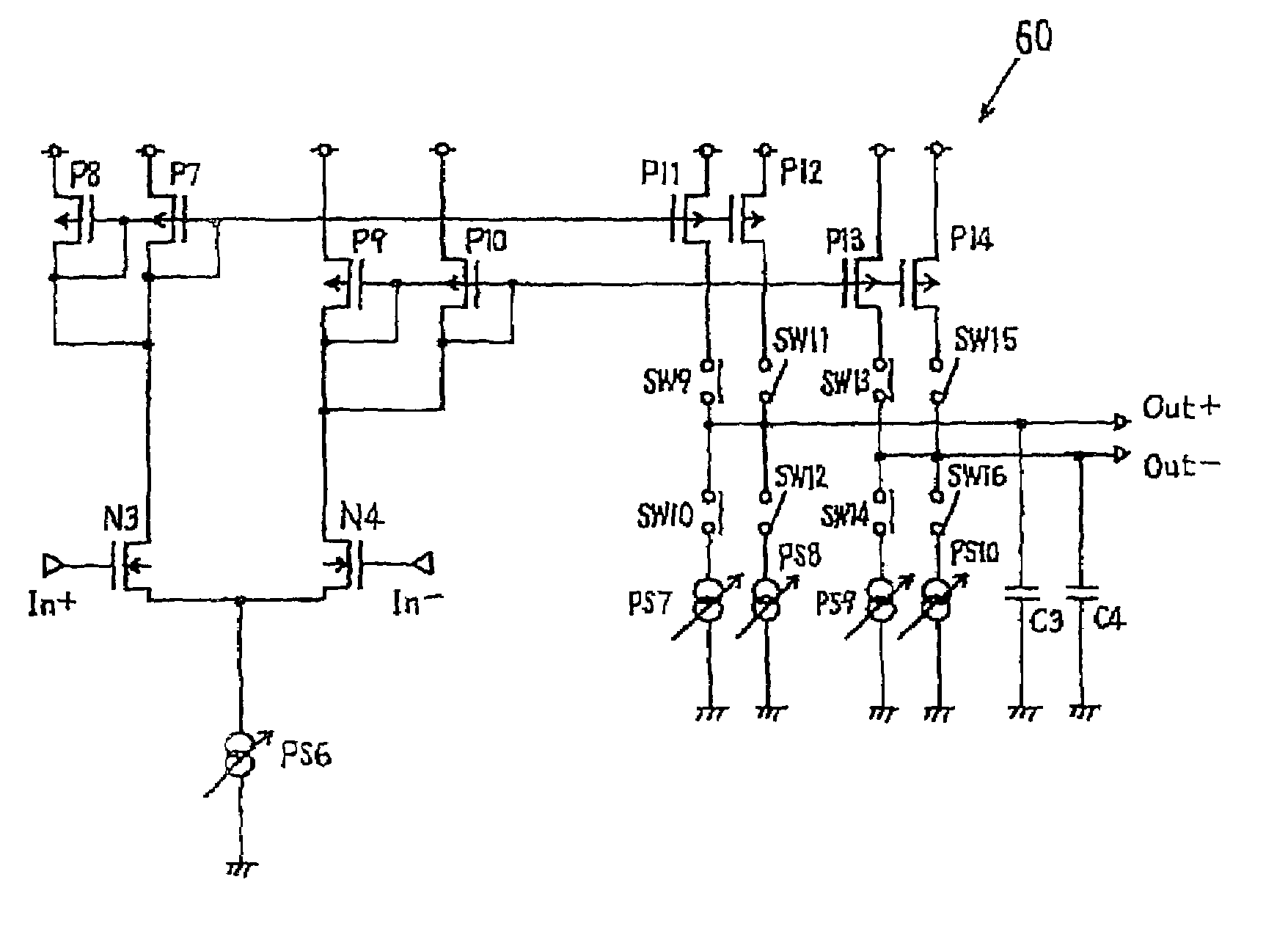
[0093]FIG. 9 shows a first example of the present invention. In this example, the cut-off frequency adjustment range is broadened by maintaining the constant current function for the transistor despite a significant current level variation. In FIG. 9, the gm filter circuit 50 automatically doubles the standard cut-off frequency.

[0094]The exemplary gm filter circuit 50 shown in FIG. 9 includes a differential input unit formed by a first N channel transistor N1 and a second N channel transistor N2. A differential input signal is fed into each transistor. A first constant current circuit is formed by a current mirror circuit. This mirror circuit outputs the first differential input signal. A second constant current circuit also is formed by a current mirror circuit. This mirror circuit outputs the second differential output signal. The filter circuit also includes a first variable current source (or constant power source) PS1; a first capacitor C1 and second capacitor C2; and a switch ...


PUM


Abstract

A trans-conductance filter circuit with an expanded cut-off frequency range is provided. The cut-off frequency of a trans-conductance filter circuit is changed by varying the current mirror ratio of a current mirror circuit. This mirror ratio is varied by changing the output current of a constant current source, or by switching among the respective action states of multiple transistors the actions of which are invoked within constant current regions. The variable cut-off frequency range can be expanded without losing the constant current attributes of the transistors.

Description

BACKGROUND OF THE INVENTION[0001]1. Field of the Invention[0002]The present invention concerns a filter circuit which is used for optical and / or magnetic recording devices such as communications equipment, audio machines, or HDD·MO, etc.[0003]2. Description of the Related Art[0004]Filter circuits are used in communications equipment or audio machines for selecting a specified frequency and removing noise. A low pass filter, for example, transmits low-band frequency signals. A high pass filter transmits high-band frequency signals. And a band pass filter transmits frequency signals within a specified frequency range.[0005]In recent years, electronic appliances must meet high precision demands, and filter circuits used in electronic circuits mounted on these electronic appliances are no exception. These filter circuits must also function effectively over a wider frequency range. The wide frequency range requirement, in particular, has become more demanding for electronic appliances an...

Claims


Application Information

Patent Timeline
Patent Type & Authority Patents(United States)
IPC IPC(8): H03H11/04H03F3/45
CPCH03F1/483H03F3/45183H03H11/0422H03F2200/36H03F2203/45288H03F2203/45646H03F2203/45726
Inventor OKADA, KOUJI
Owner FUJITSU LTD
Why Eureka
Try Eureka