
Magnetic device for a magnetic trip unit

a magnetic trip unit and magnetic device technology, applied in the direction of circuit-breaking switches, switches with electromagnetic release, protective switches, etc., can solve the problems of reducing the protection of overcurrent protection at a low current trip setting (e.g., three times the rated current of the circuit breaker), and limiting the trip set point range offered by adjusting the distance between the magnet yoke and the armature. to achieve the effect of preventing the saturation of magnetic flux

Inactive Publication Date: 2005-12-27
ABB SPA
View PDF12 Cites 10 Cited by
  • Summary
  • Abstract
  • Description
  • Claims
  • Application Information

AI Technical Summary

Benefits of technology

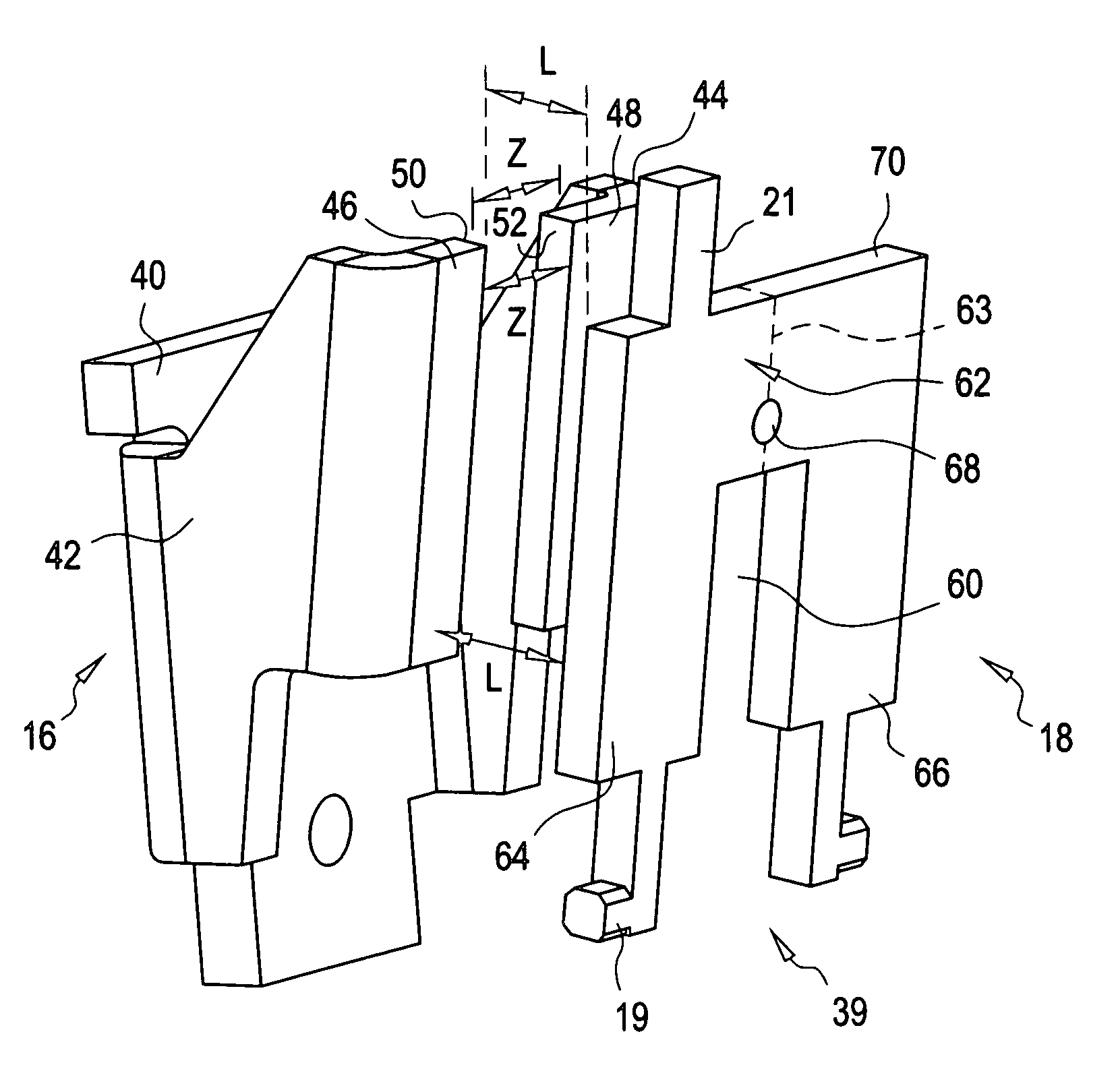
[0007]In an alternative embodiment, a method of increasing an induced magnetic force from a magnet yoke on a pivotally mounted armature of a trip unit in a circuit breaker at a low current without substantially altering the induced magnetic force acting on the armature at a high current, the method comprising: configuring the armature to provide a magnetic path having a reluctance to a magnetic flux; and adjusting the reluctance of the magnetic path to prevent saturation of the magnetic flux when a current through the trip unit is a first number times a rated current of the circuit breaker, and the magnetic path is generally saturated when the current through the circuit breaker is a second number times the rated current, wherein the first number is a number smaller than the second number.

Problems solved by technology

The trip set point range offered by adjusting the distance between the magnet yoke and the armature is limited because a large trip set point range requires a large air gap adjustment range.
Because available space is often limited, a smaller than desired adjustment range results.
Furthermore, overcurrent protection at a low current trip setting (e.g., three times the rated current of the circuit breaker) is inhibited because the magnetically induced force acting on the armature isn't significant enough to trip the latch system.

Method used


Image

  • Magnetic device for a magnetic trip unit
  • Magnetic device for a magnetic trip unit
  • Magnetic device for a magnetic trip unit

Examples


Embodiment Construction

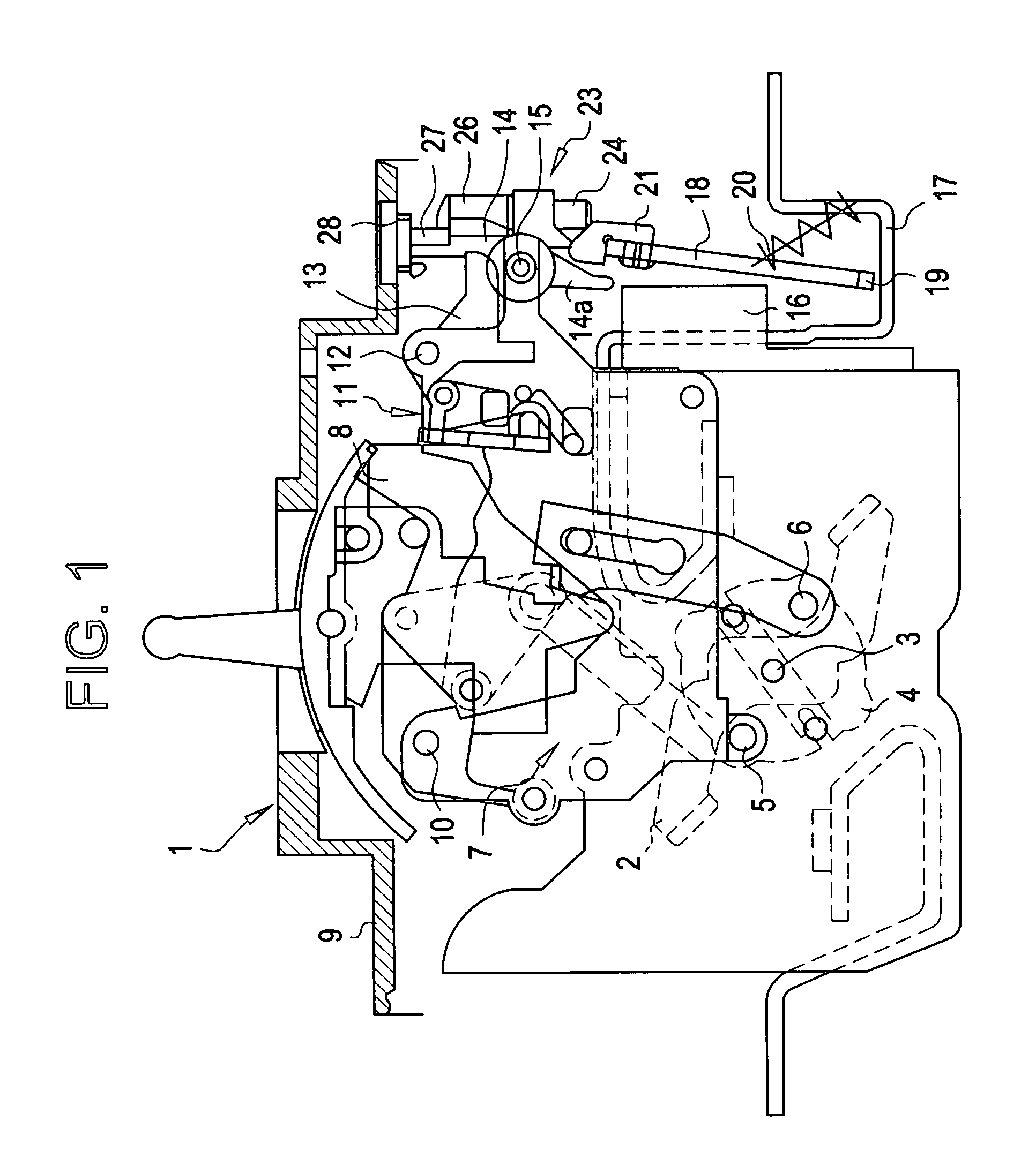
[0015]A circuit breaker 1 equipped with an adjustable magnetic trip unit of the present disclosure is shown in FIG. 1. The circuit breaker 1 has a rotary contact arm 2, which is mounted on an axis 3 of a rotor 4 such that it can rotate. The rotor 4 itself is mounted in a terminal housing or cassette (not shown) and has two diametrically opposed satellite axes 5 and 6, which are also rotated about the axis 3 when the rotor 4 rotates. The axis 5 is the point of engagement for a linkage 7, which is connected to a latch 8. The latch 8 is mounted, such that it can pivot, on an axis 10 positioned on the circuit breaker housing 9. In the event of an overcurrent or short circuit condition, the latch 8 is released by a latching mechanism 11, moving the contact arm 2 to the open position shown in FIG. 1.

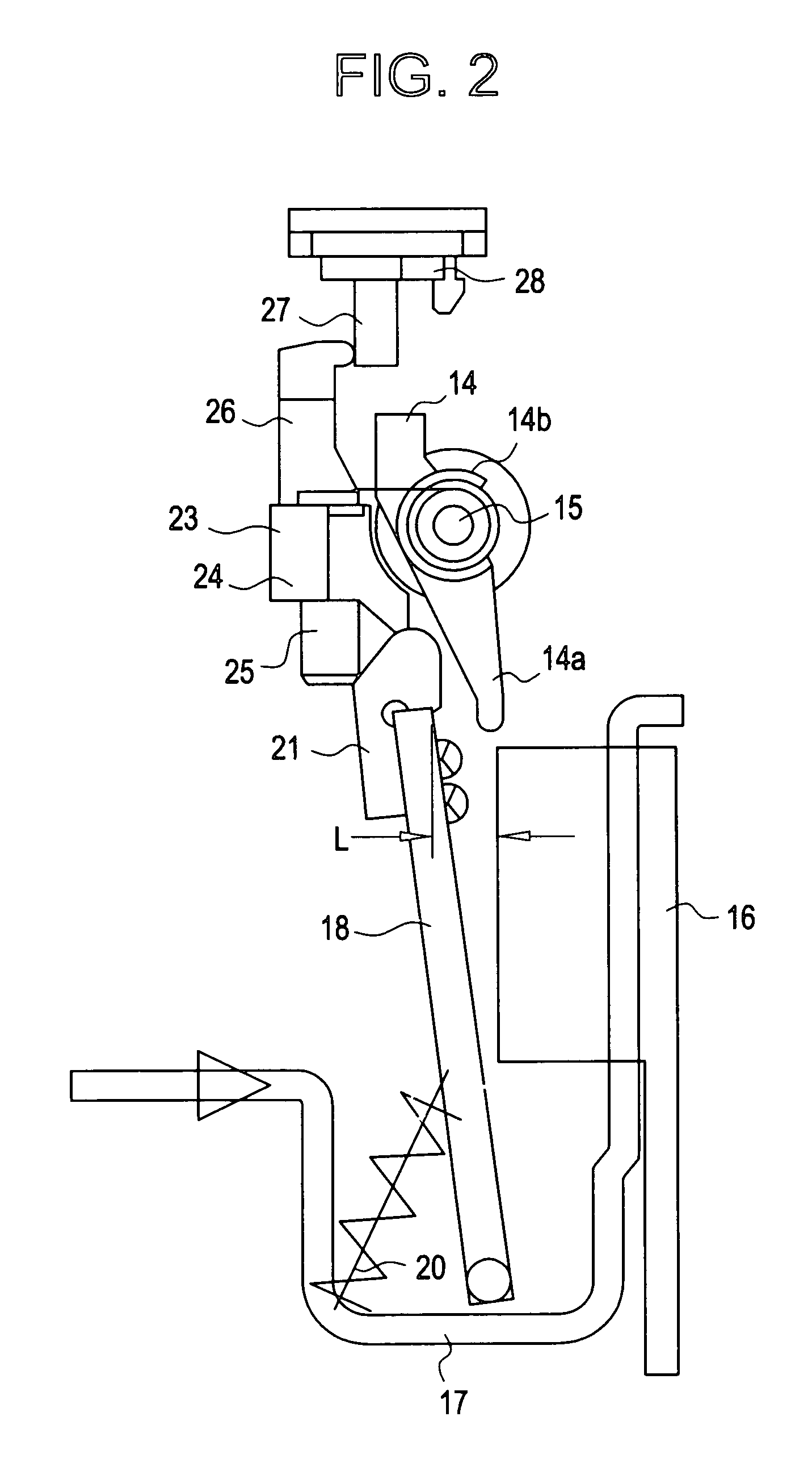
[0016]The latching mechanism 11 can be actuated by a trip lever 13 that pivots about an axis of rotation 12. The other end of the trip lever 13 contacts a trip shaft 14, which is mounted on an...


PUM


Abstract

A method and magnetic trip unit for actuating a latching mechanism to trip a circuit breaker upon an overcurrent condition, the magnetic trip unit including: a first electrically conductive strap configured to conduct an electrical current; a first magnet yoke disposed proximate to the first electrically conductive strap; and a first armature pivotally disposed proximate to the first magnetic yoke in operable communication with the latching mechanism; the first armature providing a magnetic path having a reluctance to magnetic flux; and the reluctance is adjusted to prevent saturation of the magnetic flux when the current through the strap is a first number times a rated current of the circuit breaker and the reluctance is adjusted to promote saturation of magnetic flux when the current through the strap is a second number times the rated current of the circuit breaker, wherein the first number is a number smaller than the second number.

Description

BACKGROUND OF INVENTION[0001]Circuit breakers typically provide protection against the very high currents produced by short circuits. This type of protection is provided in many circuit breakers by a magnetic trip unit, which trips the circuit breaker's operating mechanism to open the circuit breaker's main current-carrying contacts upon a short circuit condition.[0002]Modern magnetic trip units include a magnet yoke (anvil) disposed about a current carrying strap, an armature (lever) pivotally disposed near the anvil, and a spring arranged to bias the armature away from the magnet yoke. Upon the occurrence of a short circuit condition, very high currents pass through the strap. The increased current causes an increase in the magnetic field about the magnet yoke. The magnetic field acts to rapidly draw the armature towards the magnet yoke, against the bias of the spring. As the armature moves towards the yoke, the end of the armature contacts a trip lever, which is mechanically link...

Claims


Application Information

Patent Timeline
IPC IPC(8): H01H71/24H01H71/74
CPCH01H71/2436H01H71/2472H01H71/7463
Inventor O'KEEFFE, THOMAS GARYDAEHLER, CHRISTIANSAHU, BIRANCHI NARAYANADANTULURI, VARMA
Owner ABB SPA
Learn More