Electromagnetic fuel injection valve

a fuel injection valve and electromagnetic technology, applied in the direction of valve operating means/release devices, mechanical equipment, machines/engines, etc., can solve the problems of increasing the characteristics of the hinge, unstable attraction force between the stationary core and the movable core, etc., to improve the attraction force characteristics, prevent the saturation of magnetic flux, and stabilize the attraction force characteristics

Inactive Publication Date: 2008-03-13
KEIHIN CORP
View PDF2 Cites 4 Cited by
  • Summary
  • Abstract
  • Description
  • Claims
  • Application Information

AI Technical Summary

Benefits of technology

[0007] The present invention has been achieved in view of the above circumstances, and has an object to provide an electromagnetic fuel injection valve capable of preventing magnetic flux saturation from occurring in a front end wall part of a coil housing, thereby improving characteristics of attraction force between a stationary core and a movable core and also stabilizing the characteristics of the attraction force.

Problems solved by technology

However, in the front end wall part, the annular magnetic path area decreases toward the inner peripheral, and thus magnetic flux saturation occurs in the inner peripheral portion thereof, providing a factor to hinder improvement in characteristics of attraction force between a stationary core and a movable core.
Because the coil housing is press-fitted to the outer peripheral surface of a magnetic cylinder, a minor positional displacement occurs between the magnetic cylinder and coil assembly due to a press-fitting error, and this positional displacement makes unstable the characteristics of attraction force between the stationary core and the movable core.

Method used


Image

  • Electromagnetic fuel injection valve
  • Electromagnetic fuel injection valve
  • Electromagnetic fuel injection valve

Examples


Embodiment Construction

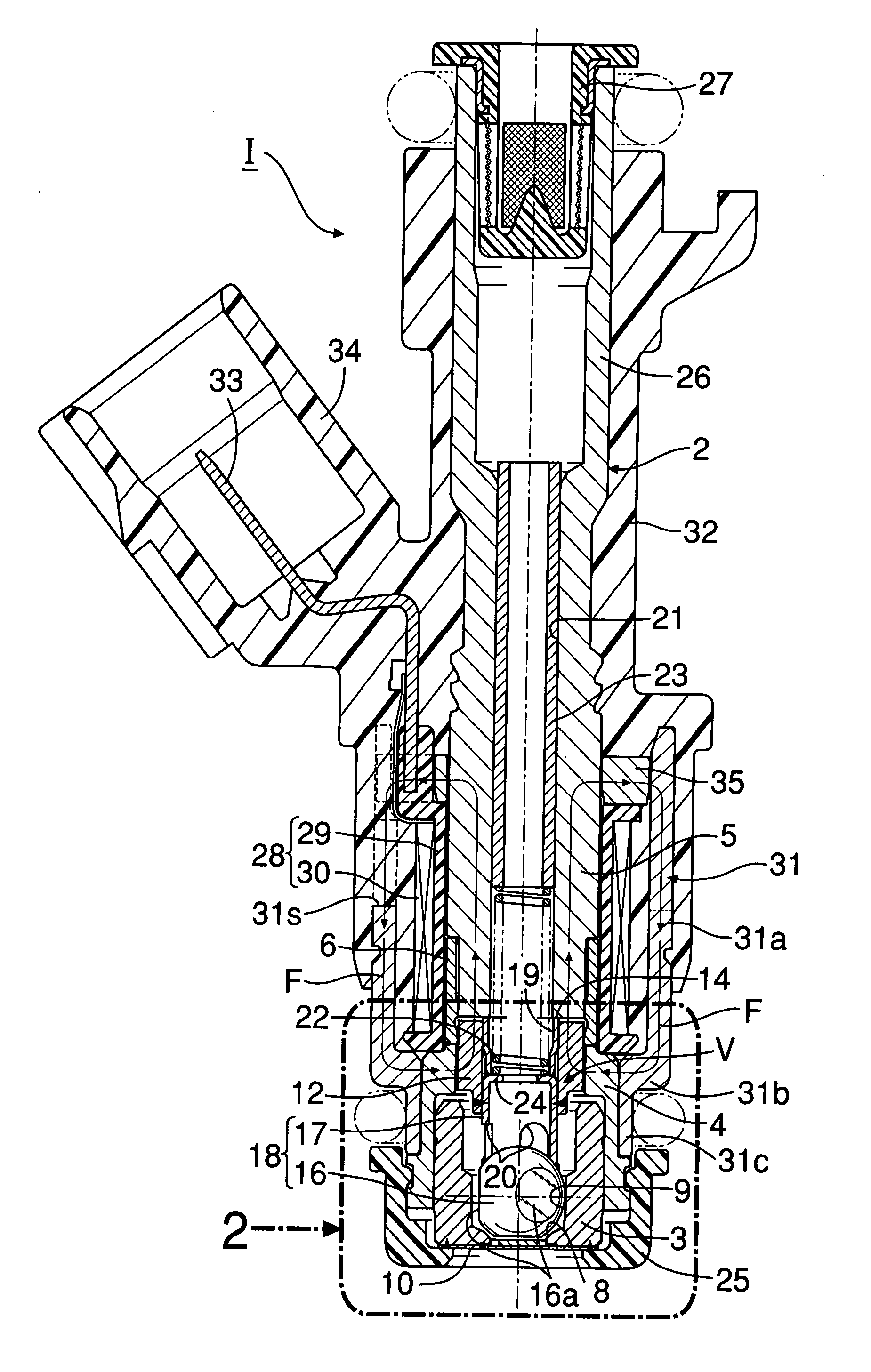
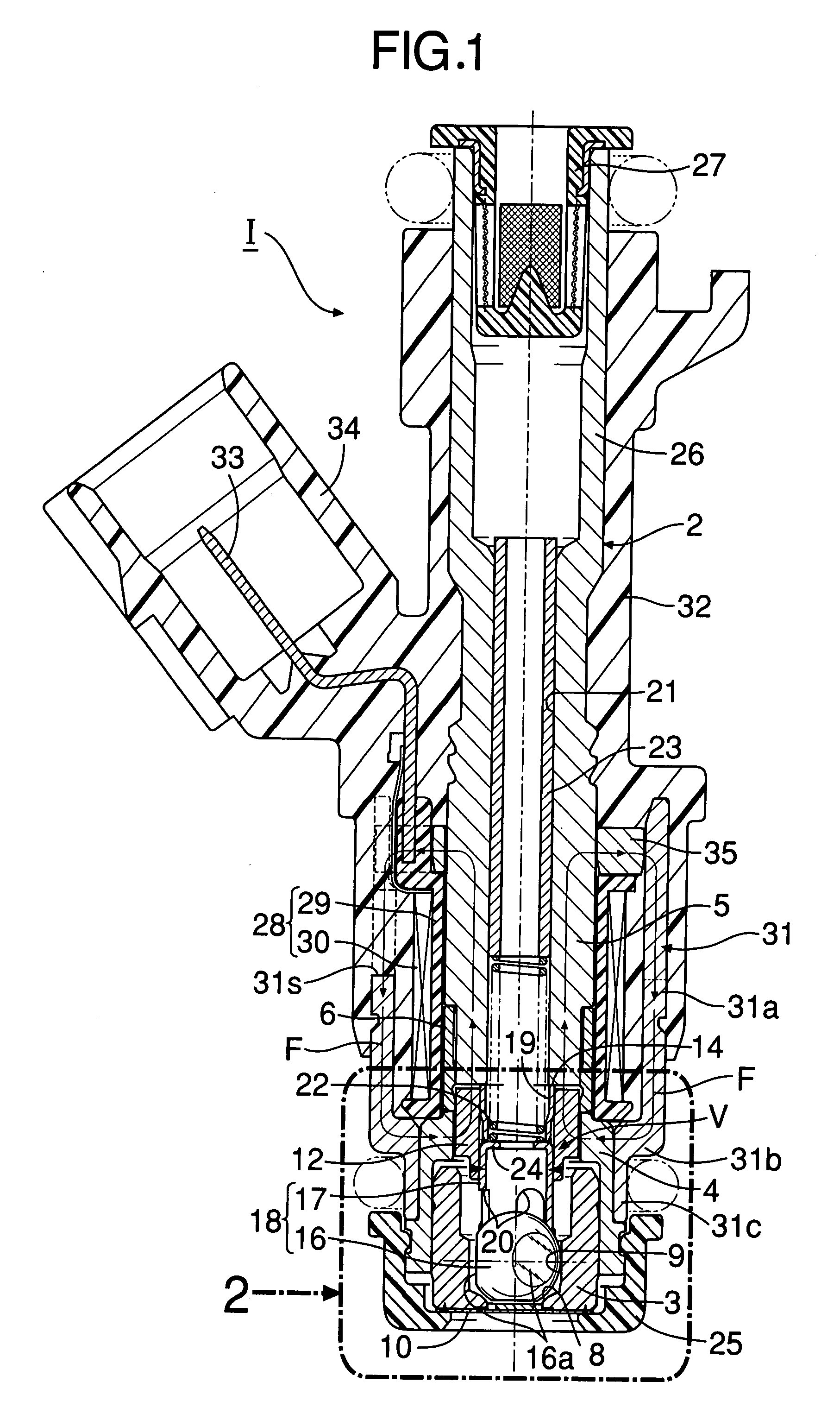
[0019] In FIG. 1, a fuel injection valve I comprises a valve housing 2 which includes a cylindrical valve seat member 3, a magnetic cylinder 4, a nonmagnetic collar 6, a stationary core 5, and a fuel inlet cylinder 26. The cylindrical valve seat member 3 has a valve seat 8 at a front end thereof. The magnetic cylinder 4 is coaxially fitted and fixed around an outer periphery at a rear end of the valve seat member 3 in a fluid-tight manner. The nonmagnetic collar 6 is coaxially joined to a rear end of the magnetic cylinder 4 in a fluid-tight manner. The stationary core 5 is coaxially fitted and fixed on an inner peripheral surface at a rear end of the nonmagnetic collar 6 in a fluid-tight manner. The fuel inlet cylinder 26 is connected coaxially and integrally at a rear end of the stationary core 5.

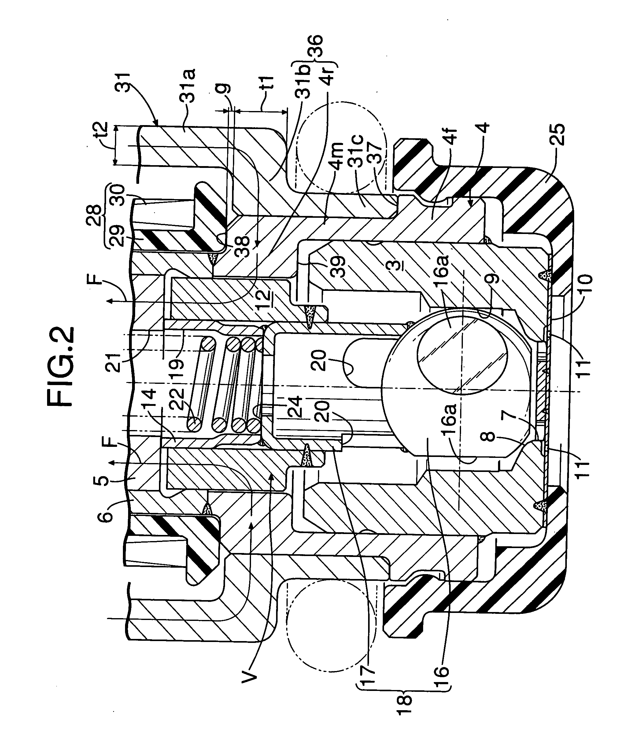
[0020] The valve seat member 3 includes a valve hole 7 penetrating a central part of the conical valve seat 8, and a cylindrical guide hole 9 connecting to a rear end of the valve seat 8....


PUM


Abstract

A valve assembly including a valve element and a movable core is housed in a valve housing including a valve seat member, a magnetic cylinder, a nonmagnetic collar and a stationary core. A coil assembly is disposed on an outer periphery of the stationary core, and housed in a coil housing. The coil housing has a front end wall part which is formed such that a thickness thereof in an axial direction is larger than a thickness of its shell part in a radial direction. A magnetic path forming part is formed by the front end wall part and a rear-side cylinder part of the magnetic cylinder which is fitted to an inner peripheral surface of the front end wall part. The magnetic path forming part surrounds the movable core substantially by the entirety of its inner peripheral surface to magnetically connect the movable core and the shell part to each other. A positioning step part is formed at a rear end of the magnetic cylinder so as to support a front end of the magnetic assembly. Thus, it is possible to prevent magnetic flux saturation from occurring in the front end wall part of the coil housing, thereby improving characteristics of attraction force between the stationary core and the movable core and also stabilizing the characteristics of the attraction force.

Description

RELATED APPLICATION DATA [0001] The present invention is based upon Japanese priority application No. 2006-234926, which is hereby incorporated in its entirety herein by reference. BACKGROUND OF THE INVENTION [0002] 1. Field of the Invention [0003] The present invention relates to a fuel injection valve mainly used in a fuel supply system of an internal combustion engine. Particularly, the present invention relates to an improvement of an electromagnetic fuel injection valve comprising: a valve housing which includes: a valve seat member having a valve seat at a front end thereof; a magnetic cylinder connected coaxially to a rear end of the valve seat member; a nonmagnetic collar connected coaxially to a rear end of the magnetic cylinder; and a stationary core fittingly fixed to a rear part of the nonmagnetic collar; a valve assembly including: a valve element capable of being seated on the valve seat; and a movable core connected to a rear end of the valve element and facing an att...

Claims


Application Information

Patent Timeline
Patent Type & Authority Applications(United States)
IPC IPC(8): F02M51/06F16K31/10
CPCF02M51/0632F02M61/1853F02M51/0682Y10S239/90
Inventor KIMURA, RYOHEIMIYASHITA, JUNICHIAOKI, RYUJI
Owner KEIHIN CORP
Why Eureka
Try Eureka