
Solid state image pickup device, driving method thereof and camera

Inactive Publication Date: 2005-12-27
SONY SEMICON SOLUTIONS CORP
View PDF10 Cites 11 Cited by
  • Summary
  • Abstract
  • Description
  • Claims
  • Application Information

AI Technical Summary

Benefits of technology

[0020]In order to solve the problem described above, according to the present invention, there are provided a solid state image pickup device in which the accumula

Problems solved by technology

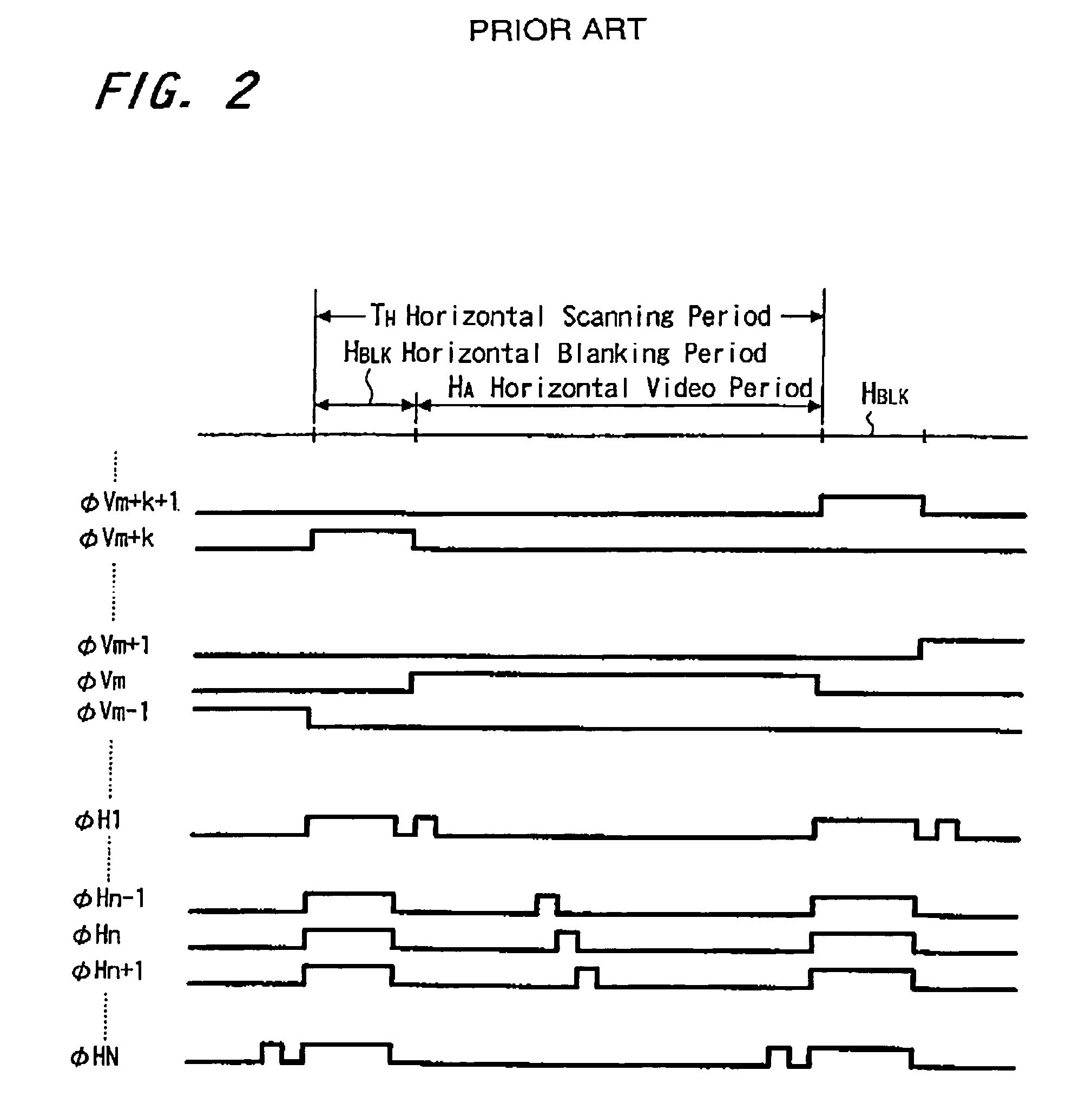
This change especially, adversely affects a solid state image pickup device in which a shutter speed is set to be high and the value of k is small.

Method used


Image

  • Solid state image pickup device, driving method thereof and camera
  • Solid state image pickup device, driving method thereof and camera
  • Solid state image pickup device, driving method thereof and camera

Examples


Embodiment Construction

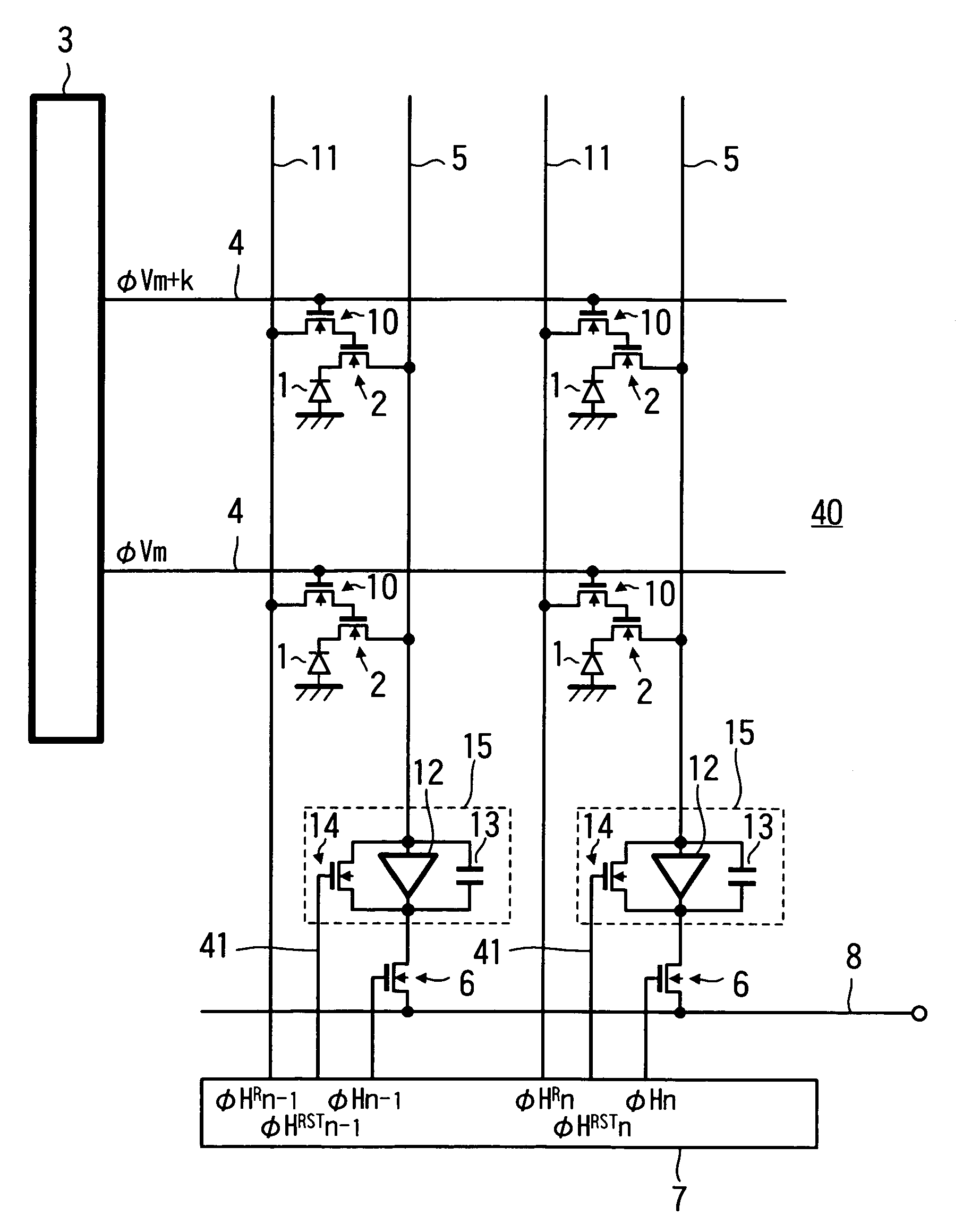
[0039]The present invention is a solid state image pickup device having a means for simultaneously performing reading of one row and an electronic shutter for the other row in a one-pixel signal period.

[0040]Further, according to the present invention, in the above-mentioned solid state image pickup device, reading of a pixel in one column in the row and an electronic shutter for a pixel in the one row in the other are row performed.

[0041]Also, according to the present invention, in the above-described solid state image pickup device, reading of a pixel in one column in one row and an electronic shutter for a pixel in a column adjacent to the one column in the other row are performed.

[0042]According to the present invention, in the above-said solid state image pickup device, the solid state image pickup device is an X-Y address type MOS or CMOS solid state image pickup device, and a read scanning pulse and an electronic shutter scanning pulse are output from both of a horizontal sca...


PUM


Abstract

There are provided a solid state image pickup device in which the accumulation time of each pixel when an electronic shutter operation is performed is constant, and a high shutter speed can be set, a driving method therefor, and a camera.A solid state image pickup device (20) having means 3, 4, 7, and 11 which simultaneously perform reading operation of one row and an electronic shutter operation for the other row in a one-pixel period P is constituted.

Description

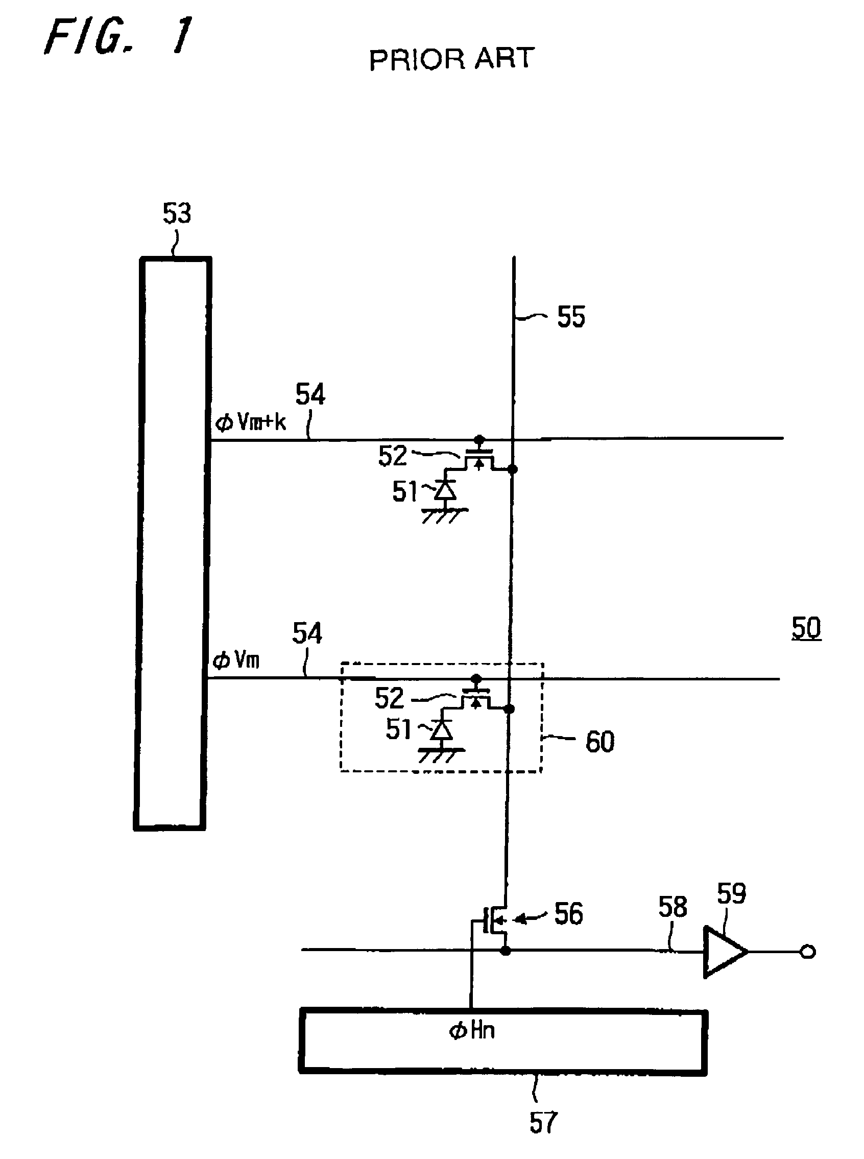
RELATED APPLICATION DATA[0001]The present application claims priority to Japanese Application No. P10 042514 filed Feb. 24, 1998 which application is incorporated herein by reference to the extent permitted by law.BACKGROUND OF THE INVENTION[0002]1. Field of the Invention[0003]The present invention relates to a solid state image pickup device constituted by an image pickup element in which pixels are arranged in, e.g., the form of a matrix, a driving method therefor, and a camera comprising an optical system and a solid state image pickup device.[0004]2. Description of the Related Art[0005]As a solid state image pickup device, there is a solid state image pickup device constituted by a so-called MOS type or CMOS type image pickup element in which each unit pixel is constituted by a having MOS transistor, a signal charge accumulated on a pixel is read by photoelectric conversion, and the signal charge is converted into a voltage to output the voltage.[0006]In the MOS type or CMOS typ...

Claims


Application Information

Patent Timeline
IPC IPC(8): H04N5/376H04N5/335H04N5/341H04N5/353H04N5/361H04N5/369H04N5/372H04N5/374H04N5/378
CPCH04N5/3532H04N5/3575H04N5/374H04N5/376H04N25/531H04N25/616H04N25/76H04N25/779H04N25/74
Inventor YONEMOTO, KAZUYAUENO, TAKAHISASUZUKI, RYOJISHIONO, KOICHI
Owner SONY SEMICON SOLUTIONS CORP
Learn More