[0058] According to an
advantage of the invention, due to its lack of
moving parts, the
solid-state flow generator of the invention can run substantially silently, is more compact, uses less power, and is more reliable than conventional mechanical flow generators. According to another
advantage, it also requires no replacement or repair of worn parts.
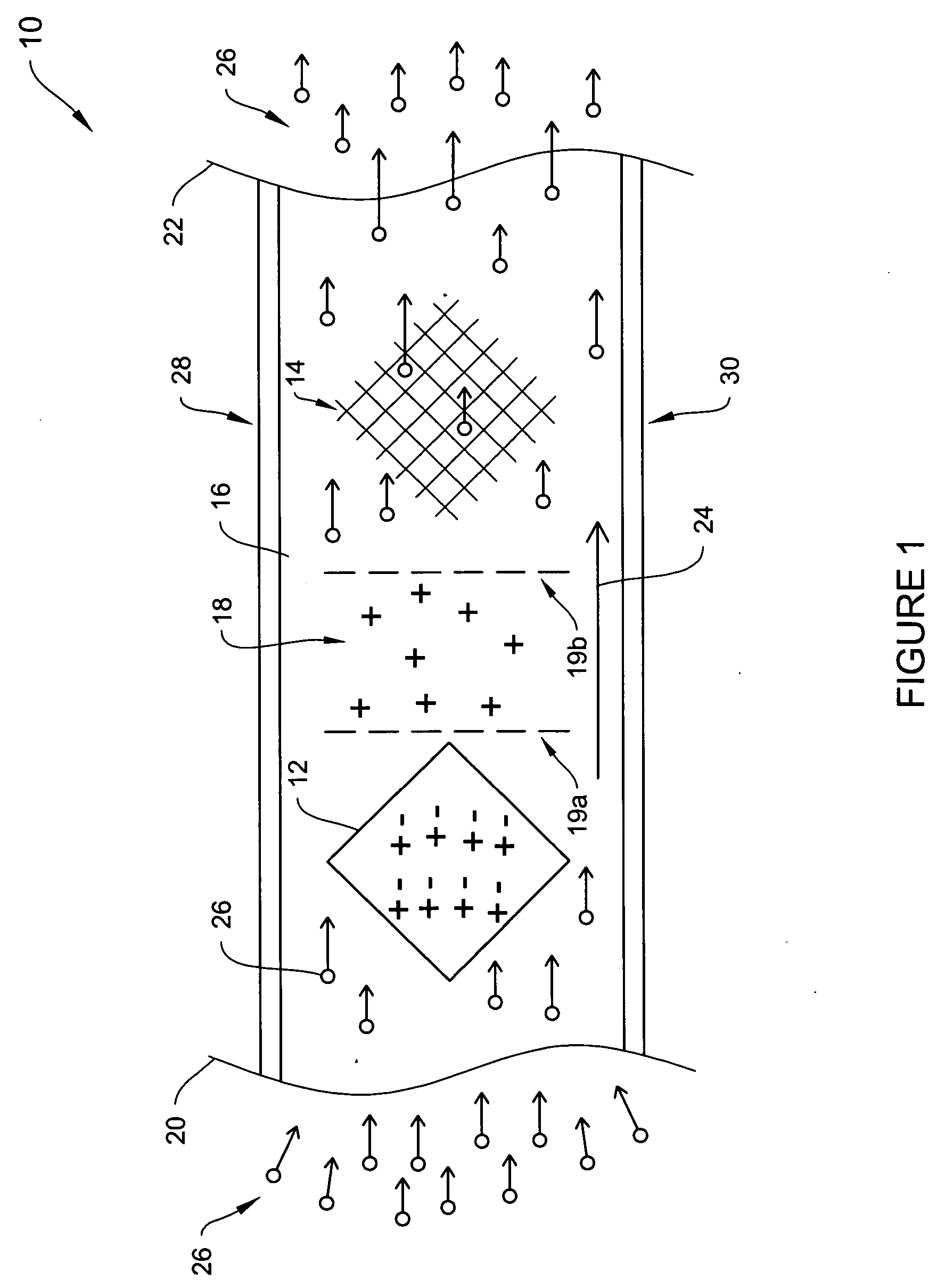
[0059]FIG. 2 is a conceptual diagram of a
fluid circulation system 30 employing a solid-state flow generator according to an illustrative embodiment of the invention. As in the case of the illustrative embodiment of FIG. 1, the solid-state flow generator of FIG. 2 includes an
ion source 32,
ion attractor 34, and a constrained flow channel 36. As described above with respect toFIG. 1, the
ion source 32 provides a source of ions and the ion
attractor 34 attracts either positive or negative ions, depending on an applied bias
voltage. The
ion flow created in the constrained channel 36 by the interaction of the
ion source 32 with the ion
attractor 34 causes a fluid flow to be created. In the instant example, a fluid is provided by an inlet 42. A
check valve 44 enables switching between introducing an external
effluent into the circulation
system 30 when the
check valve 44 is open, and re-circulating internal
effluent when the
check valve 44 is closed. The circulation
system 30 also includes a heating unit 38 and a cooling unit 40.
[0060] In operation, the
effluent in the illustrated embodiment, e.g., air, enters through the inlet 42, passes through the check valve 44, and is pulled through the constrained channel 36 past the heating 38 and the cooling 40 units, and through the ducting 46 into the space 52. The effluent circulates in a direction 48 to provide, in this case, air flow within the space 52 and eventually through the ducting 50 to the constrained channel 36 to continue the circulation cycle. The ducting 46 and 50 may be, for example, any ducting, tubing, or
piping suitable for the needs of a particular
fluid circulation system. The space 52 may be, for example, a room within a dwelling, an aircraft compartment, a vehicle compartment, or any open or
closed space or area requiring a circulated fluid. To regulate the temperature within space 52, the heating unit 38 and / or the cooling unit 40 may be activated to either heat or cool the effluent as it is circulated through the constrained channel 36. According to further illustrative embodiments, the solid-state flow generator may be located either upstream or downstream of heating unit 38 or the cooling unit 40 within constrained flow channel 36 to facilitate effluent flow in the circulation system 30. Also, additional elements may be placed within that constrained flow channel 36 or within the ducting 46 and 50 to enable, for example,
air purification,
filtration, sensing, monitoring, measuring and / or other effluent treatment.
[0061]FIG. 3 is a conceptual
block diagram of a vehicle 60 including a vehicle propulsion system 62 employing a solid-state flow generator 64 according to an illustrative embodiment of the invention. As in the case of the illustrative embodiment of FIG. 1, the solid-state flow generator 64 includes an
ion source 66, ion attractor 68, and a constrained flow channel 70. As described above with respect to FIG. 1, the
ion source 66 provides a source of ions and the ion attractor 68 attracts either positive or negative ions, depending on an applied bias
voltage. The
ion flow created in the constrained channel 70 due to the interaction of the ion source 66 with the ion attractor 68 causes a fluid flow to be created.
[0062] In operation, the effluent 72 enters the constrained channel 70 through the inlet 74, passes through the constrained channel 70, and eventually is expelled from the vehicle propulsion system 62 at the outlet 76 with a force sufficient to propel the vehicle 60. In the process of expelling effluent 72, vehicle 60 moves in a direction 78 opposite to the direction of the effluent 72 flow.
[0063] According to related illustrative embodiments, the vehicle propulsion system 62 may include multiple flow generators 64 to increase the flow of ions, resulting in an increase in the volume and / or rate of effluent 72 flow, and in increased reactive movement of the vehicle 60 in, for example, the direction 78. Because the
ion flow impels (i.e., it pushes, pulls, or otherwise influences movement of,) the effluent 72 into a flowing state, the rate and volume of which is directly related to the rate and volume of the ion flow, the greater the ion flow rate and / or flow volume, the greater the effluent 72 flow rate and / or flow volume.

