Reflection type liquid crystal projector

a liquid crystal projector and projector technology, applied in the direction of picture reproducers using projection devices, polarising elements, instruments, etc., can solve the problems of image light output efficiency degradation, high cost as optical elements, and high cost of whole optical systems

Inactive Publication Date: 2005-12-27
SANO FUJI KOKI
View PDF3 Cites 2 Cited by
  • Summary
  • Abstract
  • Description
  • Claims
  • Application Information

AI Technical Summary

Benefits of technology

[0013]The half-wave plate can be provided independently in the form of a film which is coated on a plate with flat parallel surfaces. However, it is preferable to coat a retarder film on a light incident surface of the second polarizing beam splitter. Further, the first and second polarizing be

Problems solved by technology

Naturally, the greater the number of layers, the higher becomes the cost as an optical element.
Nevertheless, in the optical arrangement according to the above-mentioned prior art, a polarizing beam splitter and a dichroic prism are partly used for reflection of p-polarization light and transmission of s-polarization light desp

Method used


Image

  • Reflection type liquid crystal projector
  • Reflection type liquid crystal projector
  • Reflection type liquid crystal projector

Examples


Embodiment Construction

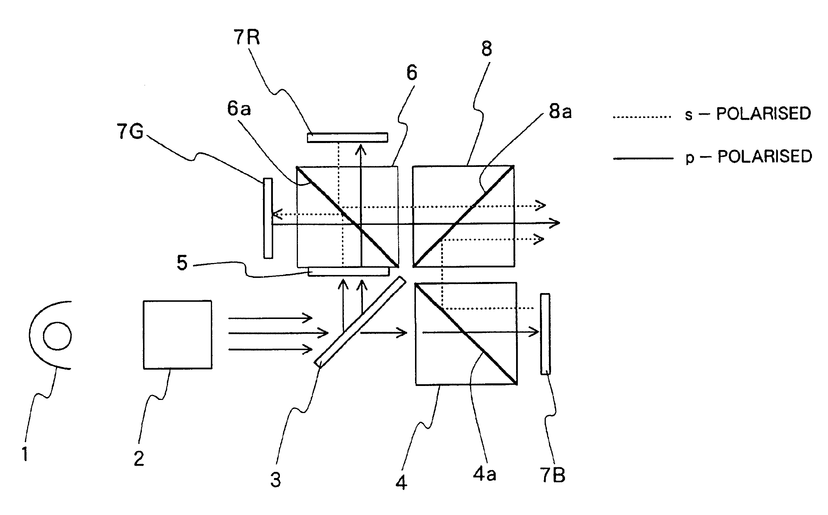
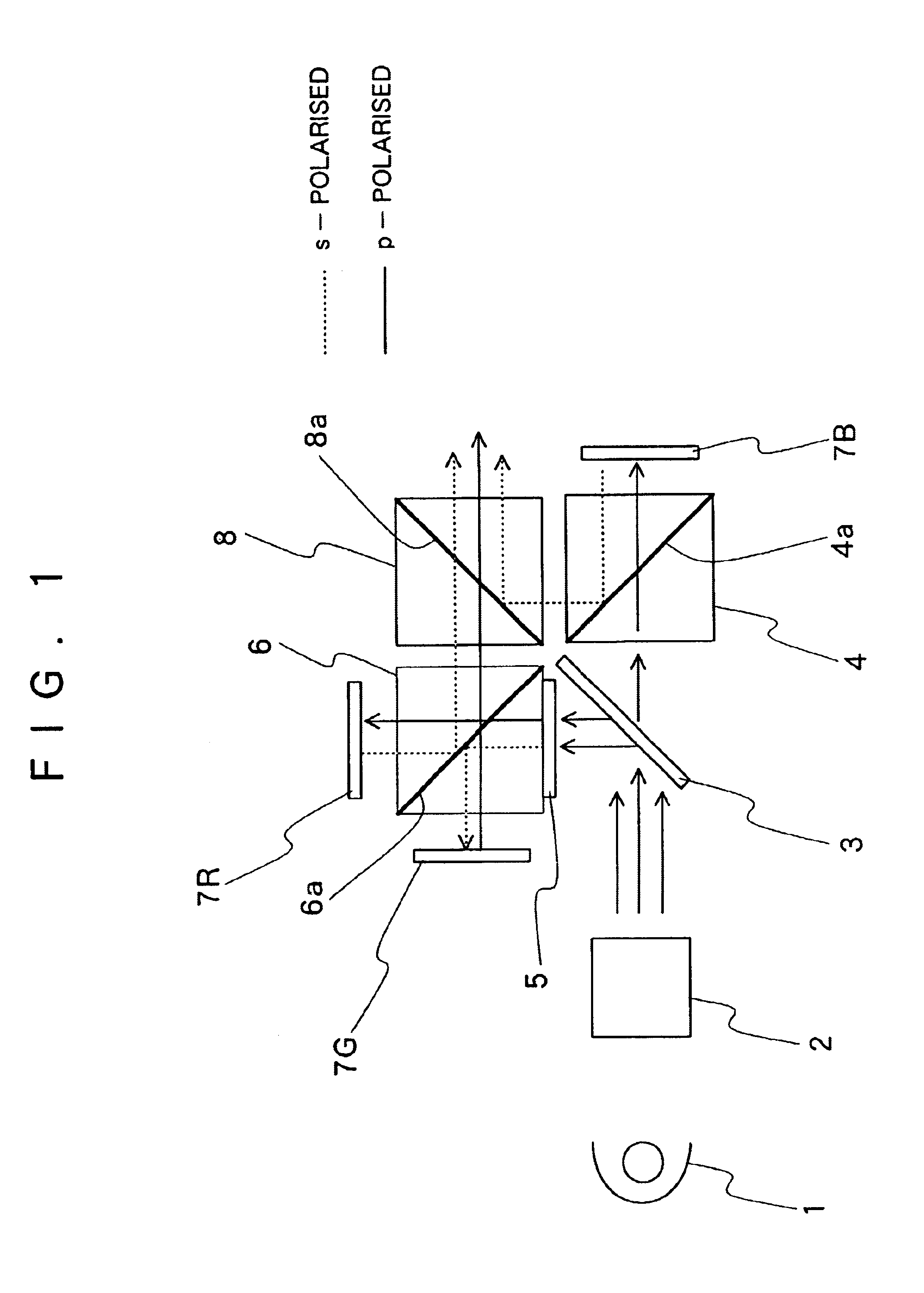
[0032]Referring to FIG. 1, there is shown a first embodiment of the present invention, in which indicated at 1 is a white light source and at 2 a polarization converting means, which constitutes an illuminating light source section along with the white light source 1. The polarization converting means 2 functions to regulate the plane of polarization of illuminating light rays from the white light source 1. In the case of the particular embodiment shown, illuminating light is regulated into p-polarized light by the polarization converting means 2.

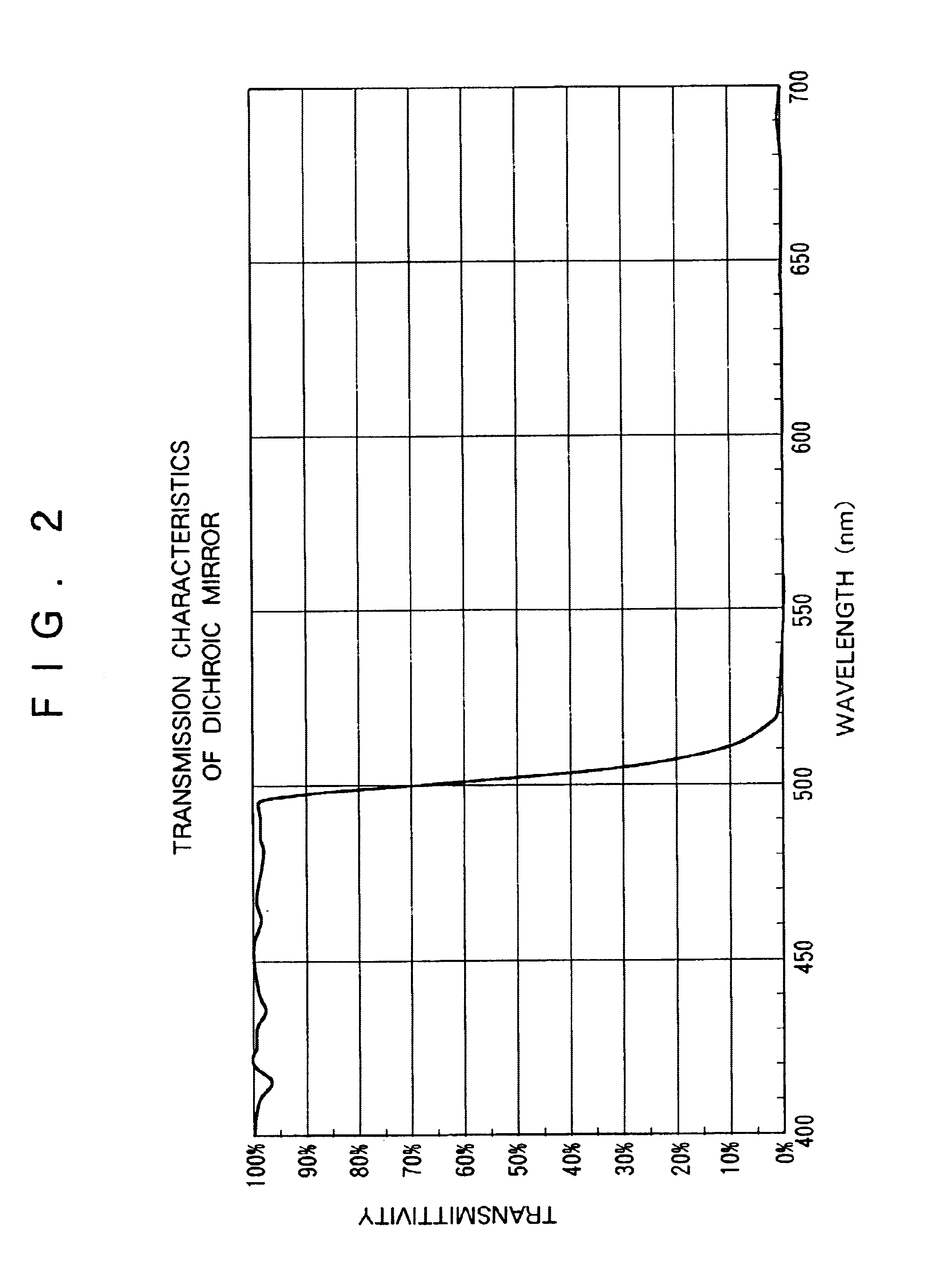
[0033]Indicated at 3 is a dichroic mirror to which illuminating light is fed in the first place. This dichroic mirror 3 serves to separate a first illuminating light component or a blue wavelength component (hereinafter referred to simply as “B component” for brevity) from a second illuminating light component or a green wavelength component (hereinafter referred to simply as “G component” for brevity) and a third illuminating light compone...


PUM


Abstract

While illuminating light is separated into a first wavelength component illuminating light and second and third wavelength component illuminating lights by a dichroic mirror, the first illuminating light is reflected off a first liquid crystal display element to form a first wavelength component image light which is then reflected off or passed through the polarizing surface of a first polarizing beam splitter, whereas one of the second and third wavelength component illuminating lights has its polarizing surface 90°-converted by a ½ phase difference plate, the other one is passed through the plate without having its polarizing surface converted, the second and third wavelength components are separated from each other by a second polarizing beam splitter and respectively reflected off second and third liquid crystal display elements to obtain second.

Description

FIELD OF THE ART[0001]This invention relates to a reflection type liquid crystal projector, and more particularly to an optical system for reflection type liquid crystal projector, adapted to project image light of three primary colors by splitting uniformly polarized white illuminating light rays into three RGB wavelength components, producing image light of three colors by reflecting the resulting three wavelength components respectively with liquid crystal display panels, and integrating the image light of the three colors together.BACKGROUND OF THE ART[0002]Optical system in existing reflection type liquid crystal projectors is basically constituted by a color separating optical system for splitting illuminating light rays from a white light source into three RGB wavelength components, three reflection type liquid crystal display panels for reflecting the separated RGB wavelength components of the illuminating light to produce image light of the respective components, and a colo...

Claims


Application Information

Patent Timeline
IPC IPC(8): G02B5/30G02B27/28G02F1/13G02B5/26G02F1/13357G02F1/13363G03B21/00G03B33/12H04N9/31
CPCG03B21/00H04N9/3105H04N9/3197G03B21/006
Inventor KATO, SHIGERUKAMEYAMA, HIROKI
Owner SANO FUJI KOKI
Why Eureka
Try Eureka