Solid immersion mirror

Active Publication Date: 2005-12-27
SEAGATE TECH LLC
View PDF12 Cites 24 Cited by
  • Summary
  • Abstract
  • Description
  • Claims
  • Application Information

AI Technical Summary

Problems solved by technology

Current conventional hard disc drive technology is limited by the superparamagnetic effect, which causes the small magnetic grains needed for high density recording media to gradually lose their magnetization state over time due to thermal fluctuations.
The lost rays in the central portion can be significant since it is likely that the intensity profile of the electromagnetic wave across the solid immersion mirror will not be uniform but rather Gaussian (or similar) so that the most intense light (near the central axis) would be lost due to the termination of the solid immersion mirror.

Method used


Image

  • Solid immersion mirror
  • Solid immersion mirror
  • Solid immersion mirror

Examples


Embodiment Construction

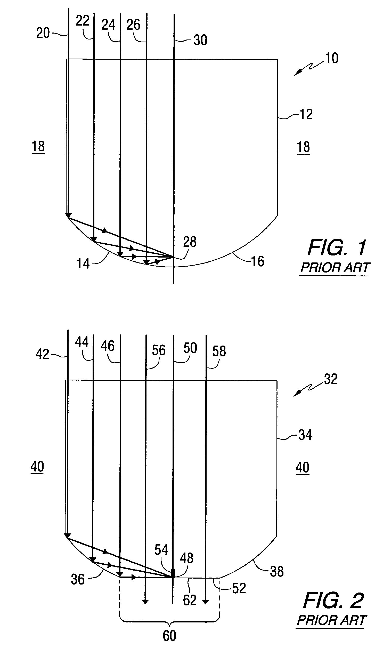
[0014]Two-dimensional planar waveguides can be used to produce focused beams of electromagnetic radiation by means of mode index lenses or planar solid immersion mirrors. The electromagnetic radiation can be, for example, ultraviolet, infrared, or visible light, but is generally referred to as light, optical rays, or a beam, in this description. Referring to the drawings, FIG. 1 is a plan view of a previously known solid immersion mirror (SIM) 10. The SIM includes a dielectric optical guiding layer 12 in a planar waveguide configuration. The guiding layer includes edges 14, 16 formed into a parabolic shape with an effective index step at the edges. The effective index step is created between the guiding layer 12 and the surrounding material 18 so that optical rays such as those identified as arrows 20, 22, 24 and 26 are directed to a focal point 28 of the guiding layer. The focal point is positioned on a central longitudinal axis 30. The effective index step can be achieved by any o...


PUM


Abstract

An apparatus for focusing electromagnetic radiation comprises a planar solid immersion mirror including edges for reflecting an electromagnetic wave toward a focal point adjacent to a truncated end of the planar solid immersion mirror, and an interface for diverting a portion of the electromagnetic wave from a central portion of the planar solid immersion mirror to the edges for subsequent reflection toward the focal point.

Description

STATEMENT REGARDING FEDERALLY SPONSORED RESEARCH OR DEVELOPMENT[0001]This invention was made with United States Government support under Agreement No. 70NANB1H3056 awarded by the National Institute of Standards and Technology (NIST). The United States Government has certain rights in the invention.FIELD OF THE INVENTION[0002]This invention relates to optical transducers that are used to focus an electromagnetic wave to a focal point, and more particularly, to such transducers that can be used in optical and / or magneto-optical storage devices.BACKGROUND OF THE INVENTION[0003]Heat assisted magnetic recording (HAMR) has been proposed as a means by which the recording density of magnetic hard disc drives may be extended to 1 Tb / in2 or higher. Current conventional hard disc drive technology is limited by the superparamagnetic effect, which causes the small magnetic grains needed for high density recording media to gradually lose their magnetization state over time due to thermal fluctuat...

Claims


Application Information

Patent Timeline
IPC IPC(8): G02B13/20G02B17/00G02B17/08G11B5/00G11B7/00G11B7/135
CPCG02B17/086G11B7/1362G11B7/1378G11B7/1387G11B11/10532G11B2005/0005G11B2005/0021
Inventor SCHLESINGER, TUVIAH EHUD
Owner SEAGATE TECH LLC
Why Eureka
Try Eureka