Switching type AC adapter circuit with a latch protection circuit

a technology of latch protection circuit and ac adapter, which is applied in the direction of dc-dc conversion, power conversion systems, instruments, etc., can solve the problems of complex structure of the primary control circuit disposed in the primary side circuit, and achieve the effect of simple structur

Active Publication Date: 2005-12-27
MITSUMI ELECTRIC CO LTD
View PDF9 Cites 42 Cited by
  • Summary
  • Abstract
  • Description
  • Claims
  • Application Information

AI Technical Summary

Benefits of technology

[0009]It is therefore an object of the present invention to provide a switching type AC adapter circuit which is simple in structure.

Problems solved by technology

However, the switching power supply apparatus disclosed in JP-A 2000-156972 is disadvantageous in that a primary control circuit disposed in the primary side circuit is complicated in structure and a different auxiliary power supply portion is required.

Method used


Image

  • Switching type AC adapter circuit with a latch protection circuit
  • Switching type AC adapter circuit with a latch protection circuit
  • Switching type AC adapter circuit with a latch protection circuit

Examples


first embodiment

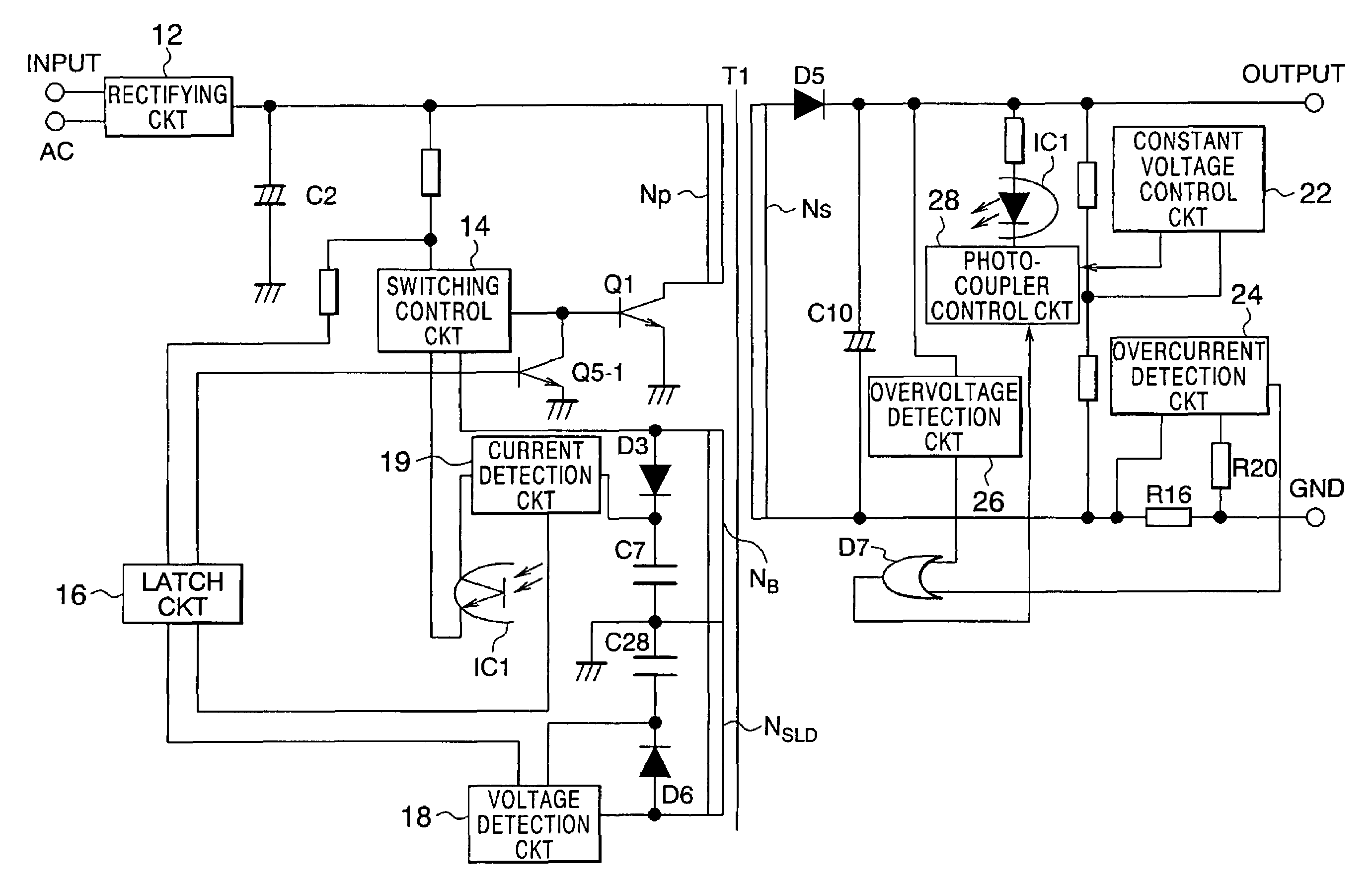
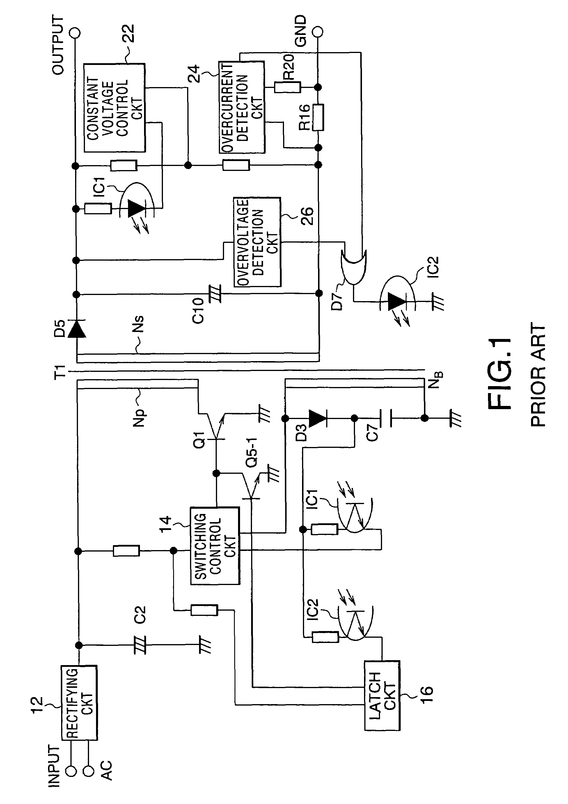
[0043]Referring to FIG. 4, the description will proceed to a switching type AC adapter circuit according to this invention. The illustrated switching type AC adapter circuit is similar in structure and operation to the conventional switching type AC adapter illustrated in FIG. 1 except that the latching photocoupler IC2 is removed, the secondary side circuit further comprises a photocoupler control circuit 28, and the primary side circuit further comprises a voltage detection circuit 18 connected to the second auxiliary winding NSLD of the transformer T1. Accordingly, similar reference symbols are attached to those having functions similar to components illustrated in FIG. 1 and description thereto is omitted in order to simplify the description.

[0044]In this invention, one photo coupler IC1 is used as a constant voltage controlling and latching photocoupler.

[0045]The photocoupler control circuit 28 is supplied with the constant voltage detection control signal from the constant vol...

second embodiment

[0059]Referring to FIG. 8, the description will proceed to a switching type AC adapter circuit according to this invention. The illustrated switching type AC adapter circuit is similar in structure and operation to the switching type AC adapter circuit illustrated in FIG. 4 except that the primary side circuit further comprises a current detection circuit 19. Accordingly, the same reference symbols are attached to those having similar functions in those illustrated in FIG. 4 and description thereto is omitted for the purpose of simplification of the description.

[0060]The current detection circuit 19 is a circuit for detecting the collector current of the phototransistor of the photocoupler IC1. When the collector current does not flow, the current detection circuit 19 makes the latch circuit 16 operate. As a result, it is possible to stop the switching operation of the switching type AC adapter circuit.

[0061]Although the switching type AC adapter circuit illustrated in FIG. 8 compri...


PUM


Abstract

Disposed in a secondary side circuit and is connected to a constant voltage control circuit (22), to an overcurrent detection circuit (24), and to an overvoltage detection circuit (26), a photocoupler control circuit (28) controls a photocoupler (IC1) so as to feed a constant voltage detection control signal as a feedback signal back to a primary side circuit. The photocoupler control circuit (28) controls the photocoupler (IC1) so as to turn it off when the photocoupler control circuit is supplied with at least one of an overcurrent detected signal and an overvoltage detected signal. A voltage detection circuit (18) makes a latch circuit (16) operate when the voltage detection circuit detects a voltage induced in an auxiliary winding (NSLD) of a transformer with the photocoupler turned off, thereby making a switching operation of a switching type AC adapter circuit stop.

Description

[0001]This application claims priority to prior Japanese application JP 2003-106346, the disclosure of which is incorporated herein by reference.BACKGROUND OF THE INVENTION[0002]This invention relates to a switching type AC adapter circuit and, in particular, to a switching type AC adapter circuit with a latch protection circuit.[0003]A switching type AC adapter circuit of the type described comprises a primary side circuit for turning, by using a switching element, a DC voltage applied to a primary winding of a transformer on and off and a secondary side circuit for rectifying and smoothing a current induced in a secondary winding of the transformer to produce a secondary side output voltage.[0004]In such a switching type AC adapter circuit, it is necessary to electrically isolate and separate the primary side circuit from the secondary side circuit in order to prevent an accident such as an electric shock. As means for electrically isolating and separating, a photocoupler or an is...

Claims


Application Information

Patent Timeline
Patent Type & Authority Patents(United States)
IPC IPC(8): H02M3/28H02M3/335
CPCH02M3/33523
Inventor NAGANO, JUNJIMURAKAMI, KOUJI
Owner MITSUMI ELECTRIC CO LTD
Why Eureka
Try Eureka