Chaotic communication system and method using modulation of nonreactive circuit elements

a communication system and non-reactive circuit technology, applied in the field of information transmission techniques, can solve the problems of a general limited modulation bandwidth available when using such techniques, and a certain amount of settling tim

Inactive Publication Date: 2005-12-27
LEIDOS
View PDF15 Cites 85 Cited by
  • Summary
  • Abstract
  • Description
  • Claims
  • Application Information

AI Technical Summary

Problems solved by technology

The modulation bandwidth available when using such techniques, however, has been determined to be generally limited to 10 to 15% of the tank circuit frequency in the transmitting circuit.
This limitation is believed to be due to the fact that changing lump parameters in the transmitter causes a certain amount of settling time before the receiver can synchronize with the changed transmitter parameters.

Method used


Image

  • Chaotic communication system and method using modulation of nonreactive circuit elements
  • Chaotic communication system and method using modulation of nonreactive circuit elements
  • Chaotic communication system and method using modulation of nonreactive circuit elements

Examples


Embodiment Construction

)

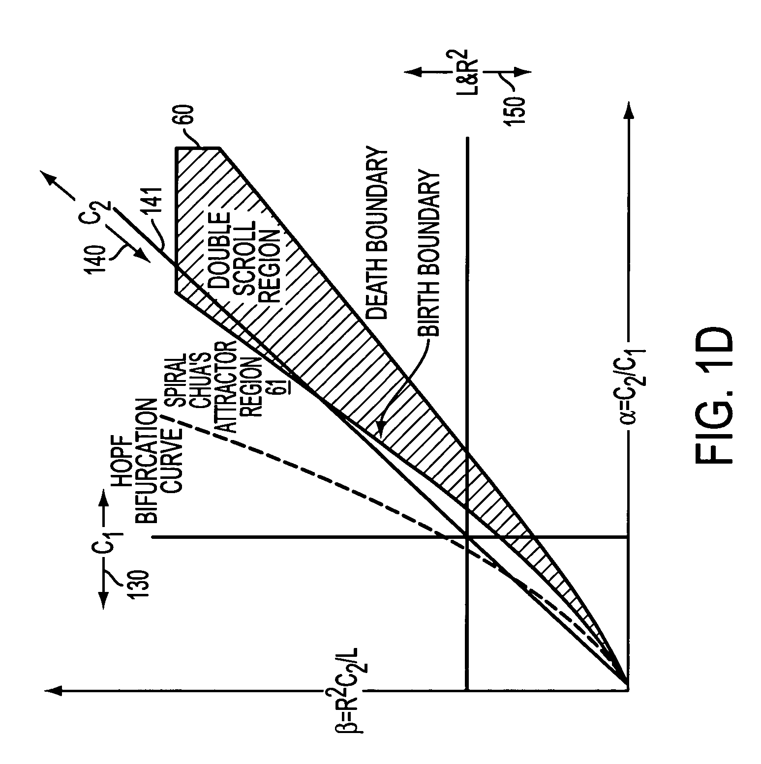
[0143]Referring again to FIG. 1D, discussed above, the various chaotic oscillating regimes of the Chua circuit are mapped onto an α / β parameter plane. Circuits falling in a double scroll region 60 are characterized by oscillation about two strange attractor equilibrium points (“double scroll”). Circuits falling in a spiral set of oscillating regimes 61 exhibit oscillation about only one strange attractor equilibrium point (“single scroll”).

[0144]The oscillations of a circuit operating in a single-scroll attractor mode can be seen graphically in FIG. 22A, which plots two voltages V1 and V2 as a function of time for a transmitter without modulation. The two voltages are measured at points 242 and 282, respectively, as shown in one embodiment of FIG. 2A. (In this example, V2 is measured at the L-C tank circuit and V1 is measured at the nonlinear resistance element). While the circuit operates in a non-modulated state, the values of V1 and V2 vary chaotically but generally swirl about ...


PUM


Abstract

A chaotic communication system employs transmitting and receiving chaotic oscillating circuits. One improvement to first-generation systems is the ability to modulate a nonreactive element in the transmitting circuit, thus increasing modulation bandwidth. Other features include insertion of a gain control amplifier in a chaotic receiver; signal filtering in chaotic transmitters and receivers; use of chaotic modulation techniques for cellular telephony applications; dual-transmitter and receiver systems; a dual receiver synchronization detector; interfaces to communication systems; analog chaotic signal modulation; use of multiple chaotic transmitters and receivers; digital algorithm improvement using a cube-law nonlinear component; a Gb-only receiver; a Gb-only transmitter; and positive slope transmitter and receiver systems.

Description

[0001]This application is a continuation-in-part of commonly-owned, U.S. application Ser. No. 09 / 116,661, now abandoned entitled “Communications System Using Chaotic Synchronized Circuits,” filed on Jul. 17, 1998 and naming as inventors Daniel E. Hinton, Sr. and Aaron Budgor. That application is incorporated into the body of this application with minor changes in the numbering of elements in the figures.TECHNICAL FIELD[0002]This invention relates generally to information transmission techniques involving modulation and demodulation of a chaotic carrier signal. Many aspects of the invention involve transmitting information by modulating various characteristics of nonreactive circuit elements of a chaotic transmitter. The invention has broad application to communications systems, radar systems and other systems that transmit and receive information over wire, radio frequencies, light (including fiber optic) and acoustic channels.BACKGROUND OF THE INVENTION[0003]Techniques for modulati...

Claims


Application Information

Patent Timeline
Patent Type & Authority Patents(United States)
IPC IPC(8): H04L9/00H04L27/00
CPCH04L27/001
Inventor HINTON, SR., DANIEL E.DEW, NELSON R.LONGTIN, LAURANCE P.GARDNER, CHARLES P.MARTIN, SHANNON W.EDWARDS, MICHAEL C.BERKLEY, ANTWONG L.BOWSER, STEVEN M.
Owner LEIDOS
Why Eureka
Try Eureka