
Flow control arrangement in a network switch based on priority traffic

a network switch and priority traffic technology, applied in data switching networks, frequency-division multiplexes, instruments, etc., can solve the problems of affecting the ability of all network switch ports to generate pause frames, affecting the ability of advanced switching operations to continue, and affecting the processing of layer 3/b> (e.g., internet protocol)

Inactive Publication Date: 2005-12-27
GLOBALFOUNDRIES US INC
View PDF13 Cites 186 Cited by
  • Summary
  • Abstract
  • Description
  • Claims
  • Application Information

AI Technical Summary

Benefits of technology

The present invention provides an arrangement for a network switch to prioritize and switch data packets without congarding network switch resources. It selectively outputs flow control frames on selected network switch ports based on the determined priority of network traffic on the selected ports. This ensures that high priority traffic is not interfered with while managing network switch resources. The invention also includes an integrated network switch with multiple network switch ports and a flow control module for selectively outputting flow control frames on a per port basis based on the determined priority of the network traffic and the depletion of network switch resources. The technical effects of the invention include improved network traffic prioritization, reduced network switch congestion, and improved network quality of service.

Problems solved by technology

Efforts to enhance the switching performance of a network switch to include layer 3 (e.g., Internet protocol) processing may suffer serious drawbacks.
In particular, the generation of pause frames on all network switch ports adversely affects attempts to maintain advanced switching operations, for example maintaining high priority traffic.
Hence, the generation of pause frames may interfere with network nodes attempting to transmit high priority traffic, resulting in a conflict between the necessity for congestion control and the necessity for maintaining reliable transport for high priority traffic.

Method used


Image

  • Flow control arrangement in a network switch based on priority traffic
  • Flow control arrangement in a network switch based on priority traffic
  • Flow control arrangement in a network switch based on priority traffic

Examples


Embodiment Construction

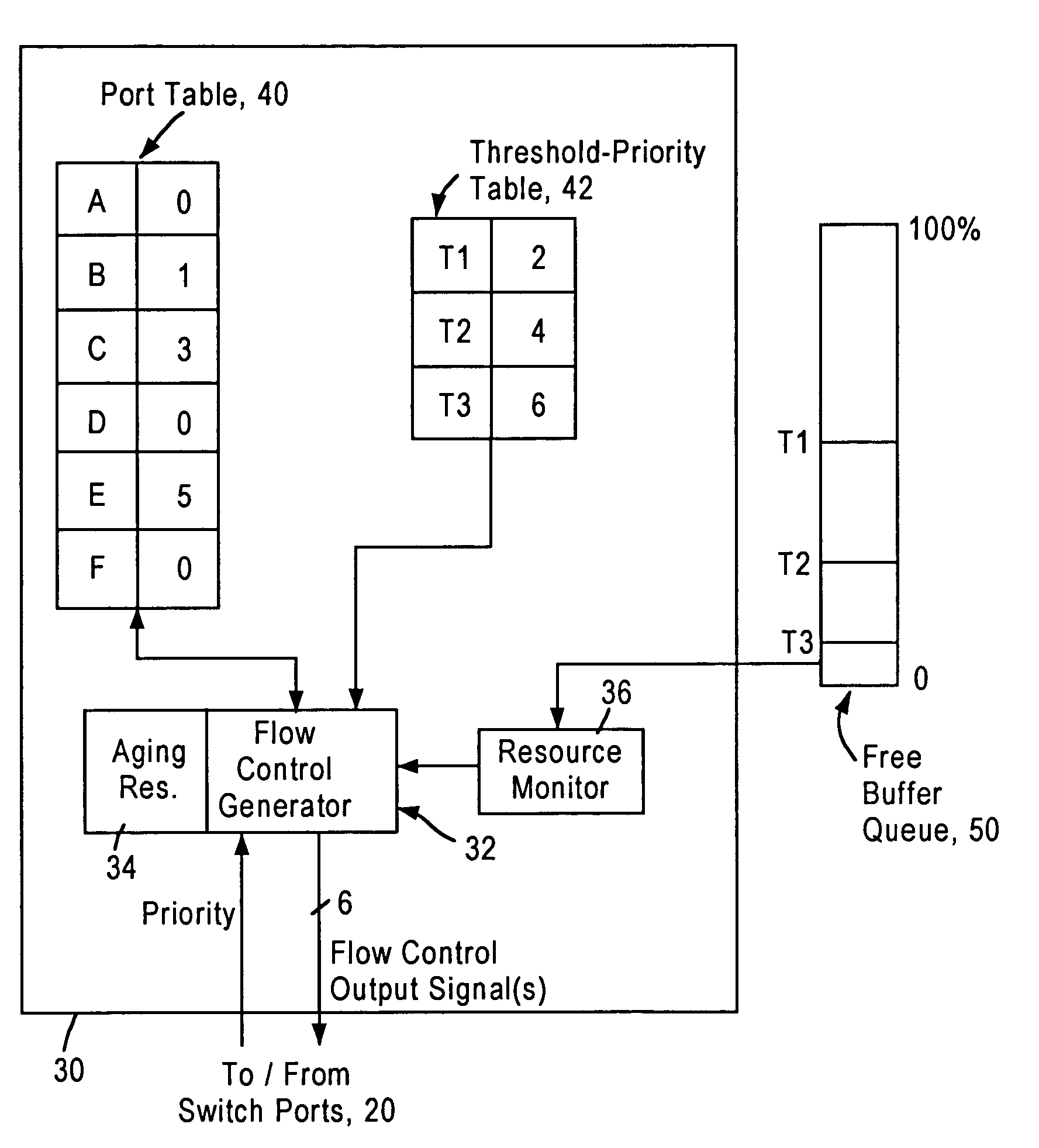
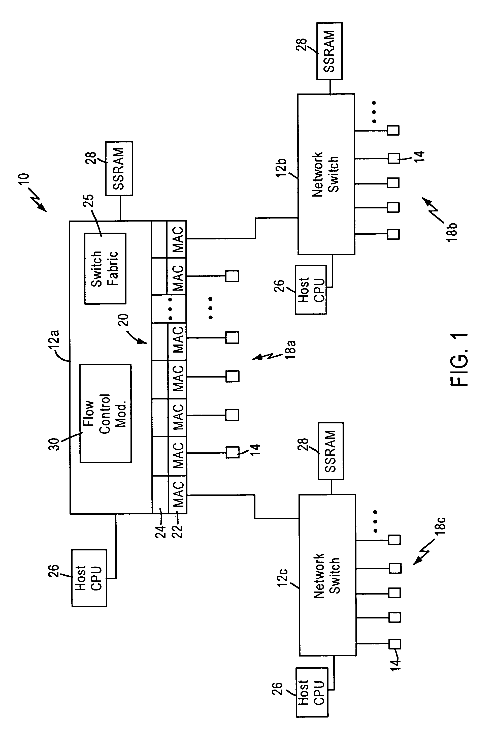
[0020]FIG. 1 is a block diagram illustrating a packet switched network 10, such as an Ethernet (IEEE 802.3) network. The packet switched network includes integrated (i.e., single chip) multiport switches 12 that enable communication of data packets between network stations 14. Each network station 14, for example a client workstation, is typically configured for sending and receiving data packets at 10 Mbps or 100 Mbps according to IEEE 802.3 protocol. Each of the integrated multiport switches 12 is interconnected by gigabit Ethernet links 16, enabling transfer of data packets between subnetworks 18a, 18b, and 18c. Hence, each subnetwork includes a switch 12, and an associated group of network stations 14.

[0021]Each switch 12 includes a switch port 20 that includes a media access control (MAC) module 22 that transmits and receives data packets to the associated network stations 14 across 10 / 100 Mbps physical layer (PHY) transceivers (not shown) according to IEEE 802.3u protocol, and...


PUM


Abstract

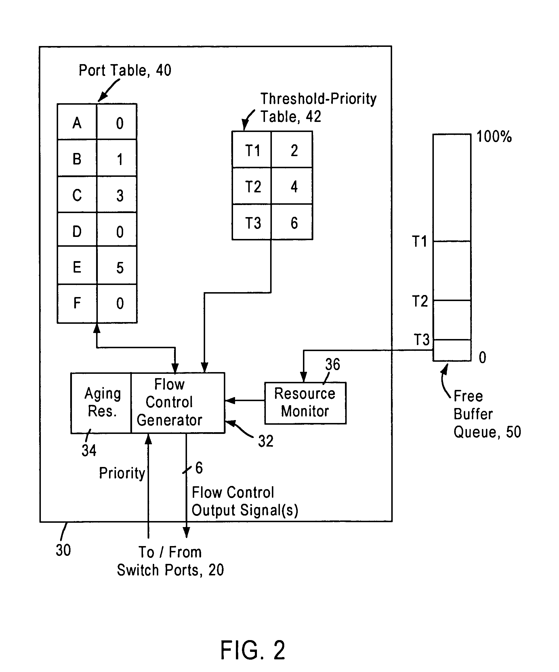
A network switch includes network switch ports, each including a port filter configured for detecting user-selected attributes from a received layer 2 frame. Each port filter, upon detecting a user-selected attribute in a received layer 2 frame, sends a signal to a switching module indicating the determined presence of the user-selected attribute, for example whether the data packet has a prescribed priority value. The network switch includes a flow control module that determines which of the network switch ports should output a flow control frame based on the determined depletion of network switch resources and based on the corresponding priority value of the network traffic on each network switch port. Hence, any network switch port that receives high priority traffic does not output a flow control frame to the corresponding network station, enabling that network station to continue transmission of the high priority traffic. In most cases, the congestion and depletion of network switch resources can be alleviated by sending flow control frames on only those network switch ports that receive lower priority traffic, enabling the network switch to reduce congestion without interfering with high priority traffic.

Description

[0001]This application claims priority from Provisional Application No. 60 / 209,582, filed Jun. 6, 2000.BACKGROUND OF THE INVENTION[0002]1. Field of the Invention[0003]The present invention relates to layer 2 switching of data packets in a non-blocking network switch configured for switching data packets between subnetworks.[0004]2. Background Art[0005]Local area networks use a network cable or other media to link stations on the network. Each local area network architecture uses a media access control (MAC) enabling network interface devices at each network node to access the network medium.[0006]The Ethernet protocol IEEE 802.3 has evolved to specify a half-duplex media access mechanism and a full-duplex media access mechanism for transmission of data packets. The full-duplex media access mechanism provides a two-way, point-to-point communication link between two network elements, for example between a network node and a switched hub.[0007]Switched local area networks are encounter...

Claims


Application Information

Patent Timeline
Patent Type & Authority Patents(United States)
IPC IPC(8): G06F3/00G06F15/16H04L12/26H04L12/28H04L12/56
CPCH04L47/10H04L47/11H04L47/2433H04L47/263H04L47/266H04L47/29
Inventor KRISHNA, GOPAL S.
Owner GLOBALFOUNDRIES US INC
Learn More