Uniform register addressing using prefix byte

a register addressing and prefix technology, applied in the field of processor register addressing, can solve the problems of byte variable registration mapping to registers, compiler design of compilers for the architecture, and registers may not be assigned to other variables, so as to simplify compiler design.

Inactive Publication Date: 2005-12-27
ADVANCED MICRO DEVICES INC
View PDF59 Cites 8 Cited by
  • Summary
  • Abstract
  • Description
  • Claims
  • Application Information

AI Technical Summary

Benefits of technology

[0007]A processor which changes the mapping of register addresses to registers dependent on an instruction field is described. In one particular embodiment, the mapping may be changed for byte addressing of the registers. A register mapping in which each register address maps to either the least significant byte or the next least significant byte of a subset of the registers may be supported, as well as a register mapping in which each register address maps to the least significant byte of each register, in one implementation. Such an implementation may, for example, maintain compatibility with the x86 byte register address mappings while allowing a more uniform mapping of byte register addresses (which may simplify compiler design). In one particular implementation, the instruction field may be a prefix field (e.g. a prefix byte).

Problems solved by technology

Unfortunately, the x86 architecture includes certain features which complicate design of compilers for the architecture.
These features complicate the compiler's mapping of byte variables to registers in several ways.
However, in this case, the registers may not be assigned to other variables if not enough byte variables are encountered.
Furthermore, mapping multiple byte variables to the same multi-byte register (since the least significant and next to least significant bytes are both byte addressable) may complicate register assignment by requiring the compiler to manage both the register name and two subfields within the register for assignment to two different byte variables.

Method used


Image

  • Uniform register addressing using prefix byte
  • Uniform register addressing using prefix byte
  • Uniform register addressing using prefix byte

Examples


Embodiment Construction

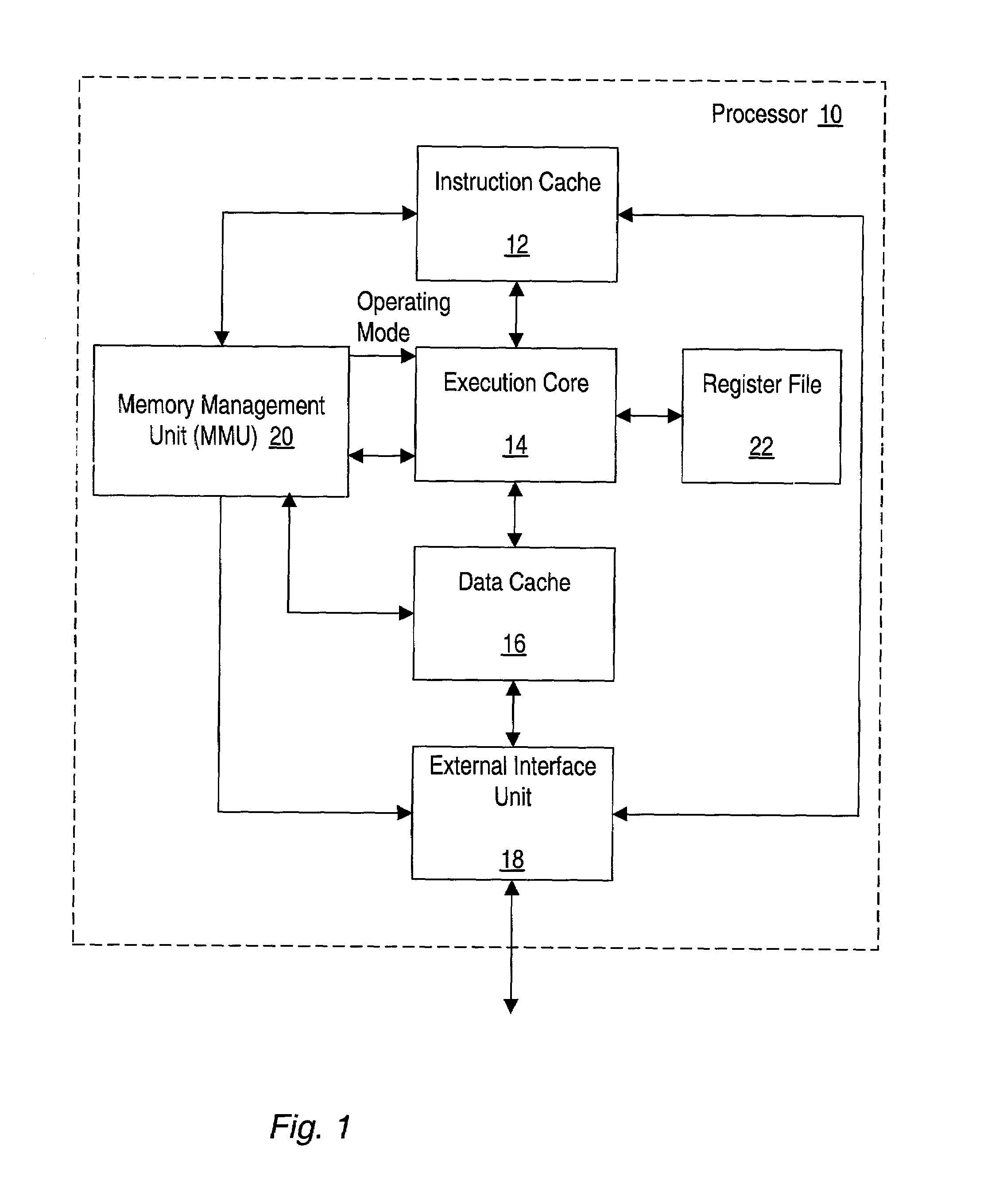
[0031]Turning now to FIG. 1, a block diagram illustrating one embodiment of a processor 10 is shown. Other embodiments are possible and contemplated. In the embodiment of FIG. 1, processor 10 includes an instruction cache 12, an execution core 14, a data cache 16, an external interface unit 18, a memory management unit (MMU) 20, and a register file 22. Instruction cache 12 is coupled to external interface unit 18, execution core 14, and MMU 20. Execution core 14 is further coupled to MMU 20, register file 22, and data cache 16. Data cache 16 is further coupled to MMU 20 and external interface unit 18. External interface unit 18 is further coupled to MMU 20 and to an external interface.

[0032]Processor 10 is configured to establish an operating mode. As used herein, an “operating mode” specifies default values for various programmably selectable processor attributes. For example, the operating mode may specify a default operand size and a default address size. The default operand size...


PUM


Abstract

A processor changes the mapping of register addresses to registers dependent on an instruction field. In one particular embodiment, the mapping may be changed for byte addressing of the registers. A register mapping in which each register address maps to either the least significant byte or the next least significant byte of a subset of the registers may be supported, as well as a register mapping in which each register address maps to the least significant byte of each register, in one implementation. In one particular implementation, the instruction field may be a prefix field (e.g. a prefix byte). The processor may provide for uniform addressing of registers (e.g. byte addressing of the registers) responsive to a prefix field, in other embodiments, irrespective of the addressing provided if the prefix field is not included, or is encoded differently than the encoding which results in the uniform addressing.

Description

[0001]This application claims benefit of priority to Provisional Application Ser. No. 60 / 224,368 filed Aug. 9, 2000.BACKGROUND OF THE INVENTION[0002]1. Field of the Invention[0003]This invention is related to the field of processors and, more particularly, to register addressing within processors.[0004]2. Description of the Related Art[0005]The x86 architecture (also known as the IA-32 architecture) has enjoyed widespread acceptance and success in the marketplace. Accordingly, it is advantageous to design processors according to the x86 architecture. Such processors may benefit from the large body of software written to the x86 architecture (since such processors may execute the software and thus computer systems employing the processors may enjoy increased acceptance in the market due to the large amount of available software).[0006]Unfortunately, the x86 architecture includes certain features which complicate design of compilers for the architecture. For example, it is sometimes d...

Claims


Application Information

Patent Timeline
Patent Type & Authority Patents(United States)
IPC IPC(8): G06F9/30G06F9/318
CPCG06F9/30036G06F9/30098G06F9/3013G06F9/30138G06F9/3016G06F9/30167G06F9/30185G06F9/30189G06F9/342G06F9/384G06F9/30181
Inventor CHRISTIE, DAVID S.MCGRATH, KEVIN J.
Owner ADVANCED MICRO DEVICES INC
Why Eureka
Try Eureka