Extrusion container

a container and container body technology, applied in the field of extrusion containers, can solve the problems of preventing smooth extrusion operation and high amount of unused contents, and achieve the effect of decreasing tension

Inactive Publication Date: 2006-01-03
YOSHINO KOGYOSHO CO LTD
View PDF5 Cites 1 Cited by
  • Summary
  • Abstract
  • Description
  • Claims
  • Application Information

AI Technical Summary

Benefits of technology

[0019]Though the tension that acts on the non-adhered inner layer parts arises since the outer shell layer is not readily displaced at the vicinity of the adhesive bands that are integrally joined to the inner layer, by setting, as in the arrangement of the first claim, the rigidity of the outer shell layer so that, in the state where tension arises at the side end parts of the adhesive bands, the outer shell layer can be deformed by this

Problems solved by technology

However in regard to the width dimension of each adhesive band, if the width is too wide, adequate deflation of the inner container body cannot be accomplished, and oppositely if the width is too n

Method used


Image

  • Extrusion container
  • Extrusion container
  • Extrusion container

Examples


first embodiment

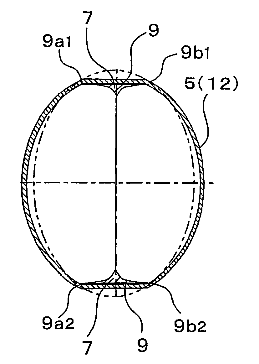
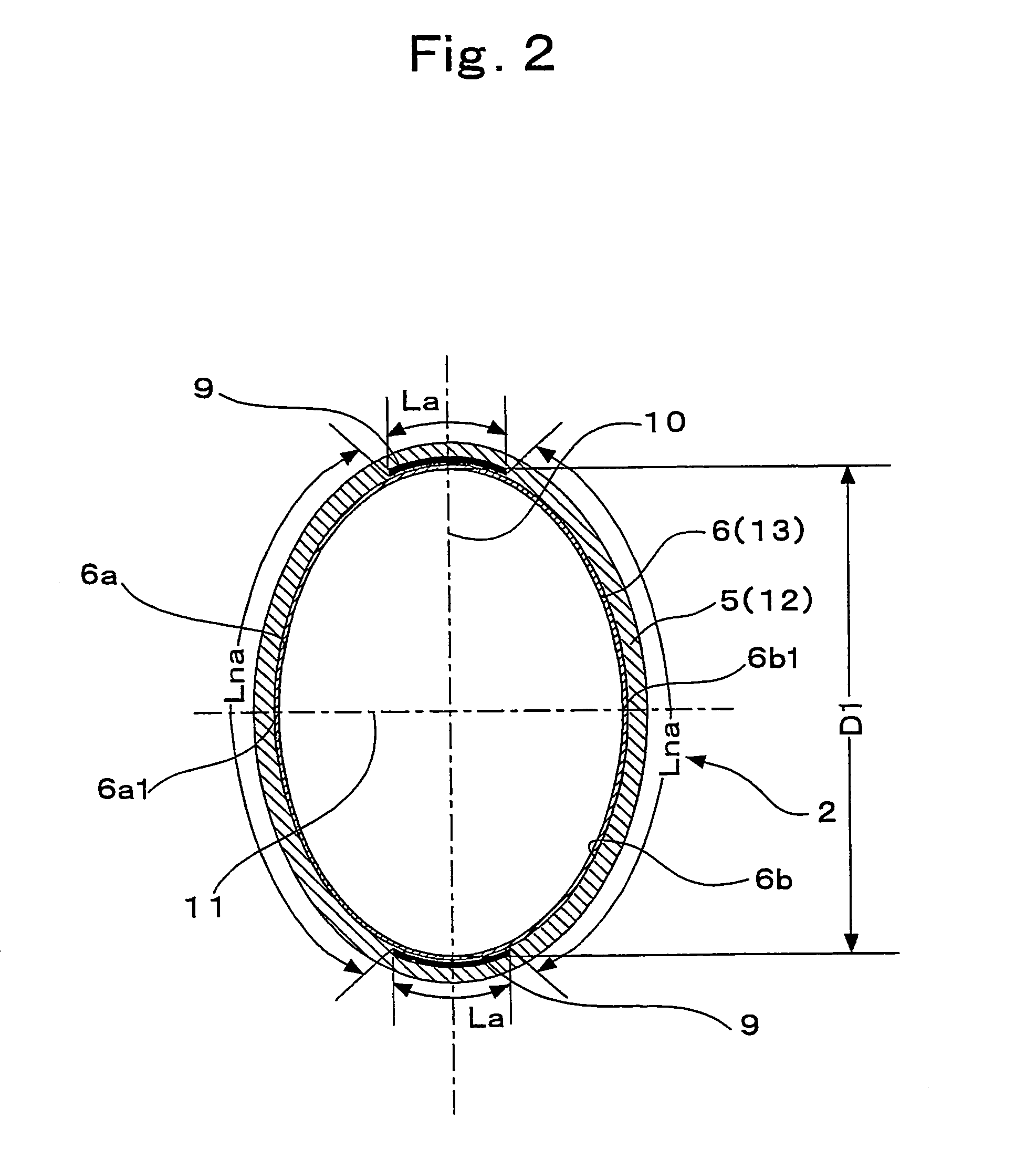
[0047]FIGS. 1 through 6 show an extrusion container by this invention, and this extrusion container comprises a main container body 1 and an extrusion cap body 20 with main container body 1 in turn comprising an outer shell layer 5, made of a low-density polyethylene resin, and an inner layer 6, made of an eval resin (made by Kuraray Co., Ltd.), which is an ethylene vinyl alcohol copolymer that is low in compatibility with the low-density polyethylene resin, and two adhesive bands 9 of longitudinal band form that adhere outer shell layer 5 and inner layer 6 together are formed along the entire height range from an adhesive resin that exhibits adequate adhesion to the low-density polyethylene resin and the eval resin.

[0048]The resins used for outer shell layer 5 and inner layer 6 are not restricted to low-density polyethylene resin and eval resin, and resins that are mutually low in compatibility may be selected and used according to the purpose.

[0049]Main container body 1 has a bott...

second embodiment

[0071]FIGS. 7 to 9 show this invention's extrusion container.

[0072]This extrusion container of the second embodiment of this invention is the same in arrangement as the first embodiment with the exceptions that the sectional shape of body 2, which shall be described in detail below, is a circular shape, three adhesive bands 9 are formed, and in correspondence to these three adhesive bands 9, external air introduction holes 8a are opened at three locations of mouth part 3 and second non-return function part 26 has second non-return valves 26a attached to three locations of the cylindrical wall of main cap body 21.

[0073]Main container body 1 has a height of 160 mm, body 2 has a circular plane cross-sectional shape with a diameter D (inner diameter) of 55 mm, outer shell layer 5, inner layer 6, and adhesive bands 9 are respectively formed from the same resins as those of the first embodiment, and the average thickness of outer shell layer 5 at body 2 is 1.0 mm.

[0074]FIG. 8 shows a plan...


PUM


Abstract

An extrusion container comprises a main container body with a squeezable outer shell layer and an extrusion cap body, and at least two adhesive bands of longitudinal band form, each of which adheres and fixes together the outer shell layer and an inner layer along the entire height range, wherein the width of each adhesive band is set so as to disable complete closure of the plane cross section by free deformation of non-adhered inner layer parts, and a rigidity of the outer shell layer is set so that, in the state where free deformation of the non-adhered inner layer parts reaches a limit, deformation of the outer shell layer by tension at the non-adhered inner layer parts occurs as a result of normal squeezing operation by a human hand, whereby an extrusion path and smooth extrusion operation is maintained and residual contents is reduced.

Description

TECHNICAL FIELD[0001]This invention relates to in a separably laminated synthetic resin blow molded container, with which a deflatable inner container body is separably laminated inside a squeezable outer container body, a synthetic resin extrusion container with which use, that is, extrusion of the contents is facilitated.BACKGROUND ART[0002]Laid-open Japanese Utility Model Publication No. Sho 57-44063 and Laid-open Japanese Utility Model Publication No. Hei 7-22951 disclose squeeze-type extrusion containers that comprise an inner container body and an outer container body that contains the inner container body.[0003]With the extrusion container disclosed in Laid-open Japanese Utility Model Publication No. Sho 57-44063, a ventilation hole is provided at the bottom part of a main container body so that after extrusion of contents by squeezing of the main container body, external air is introduced between an outer container body and an inner container body so that while keeping the d...

Claims


Application Information

Patent Timeline
IPC IPC(8): B65D37/00B65D1/32B65D35/50B65D47/20B65D77/06B65D83/00
CPCB65D1/32B65D47/2018B65D83/0055B65D2231/005B65D2231/00
Inventor NAKAMURA, HIROYUKIYONEYAMA, MASASHIGOTO, TAKAYUKI
Owner YOSHINO KOGYOSHO CO LTD
Why Eureka
Try Eureka