Colonoscope handgrip with force and torque monitor

a technology of force and torque and monitor, which is applied in the field of colonoscopy handgrip with force and torque monitor, can solve the problems of excessive force, variation in force applied, and pain in force applied to the colon and its anatomic attachment, and achieve the effects of reducing the risk of infection

Inactive Publication Date: 2006-01-03
ARTANN LAB
View PDF15 Cites 115 Cited by
  • Summary
  • Abstract
  • Description
  • Claims
  • Application Information

AI Technical Summary

Benefits of technology

[0012]It is another object of the present invention to provide a force and torque indicating handgrip, which can be easily used with a variety of commercially available scope instruments.
[0013]It is a further object of the present invention to provide a handgrip adapted for sliding along the shaft of the colonoscope during its insertion and removal so that the area of grip by the hand of the operator can be changed depending on the clinical necessity.
[0014]It is yet a further object of the present invention to provide a handgrip, which can be reused multiple times and can withstand disinfection and sterilization by all commonly used methods without the loss of sensitivity or any undesirable change in force and torque indication.
[0015]The handgrip of the invention consists of an internal sleeve an...

Problems solved by technology

When using a colonoscope, a common problem is to be able to maneuver the inspection end of the scope and position it in proximity to the area of interest.
The application of force to the colon and its anatomic attachments can be painful.
Particularly undesirable is the frequent occurrence of excessive contact pressure on an internal tissue, which can result in perforation.
Preliminary studies suggest that there is significant variation in the forces applied and that these forces can be excessive.
Operator training programs are designed to reduce the variation in technique, however training metrics remain subjective and the characterization of effective, less forceful insertion methods is not yet available.
PCT W088/00810 of Tenerz et al. entitled “Guide F...

Method used


Image

  • Colonoscope handgrip with force and torque monitor
  • Colonoscope handgrip with force and torque monitor
  • Colonoscope handgrip with force and torque monitor

Examples


first embodiment

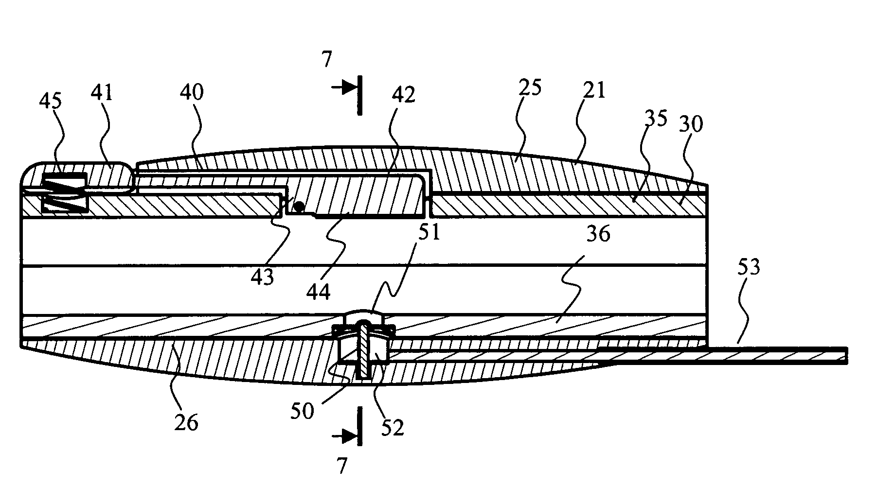
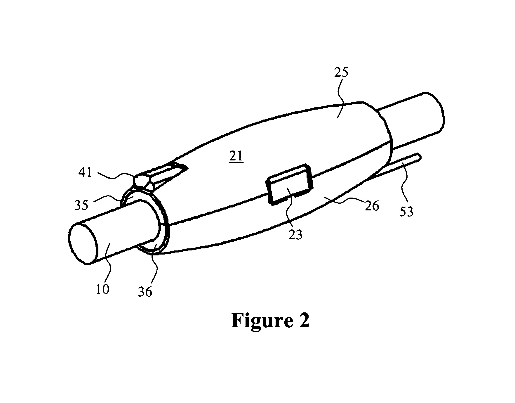
[0043]The handgrip 20 will now be described in more detail. the handgrip is shown in greater detail on FIGS. 2–7. The handgrip 20 consists of an external sleeve 21 slidingly positioned over an internal sleeve 30 with an engaging means 50 located therebetween. The external sleeve 21 has a shape adapted for easy grip by a human hand as shown on FIGS. 2 and 6. In its preferred configuration, the shape of the external sleeve is such that it covers almost entirely the internal sleeve 30 so that the operator holds the entire device only by the external sleeve. To allow its placement over the shaft 10 of the colonoscope, the external sleeve 21 is made in two halves 25 and 26 connected together on one side by a spring 22 biased in a way as to allow them to open when the clamp 23 is released. The spring 22 is also positioned to allow one half of the external sleeve to swing away and towards another. Alternatively, the halves 25 and 26 may be molded from a polymer material with a living hinge...

third embodiment

[0055]The engaging means is arranged as a combination of radial 254 and longitudinal 255 sets of engaging plates. Each plate is equipped with a sensor to measure its deflection as a function of force applied to one side of this plate. Strain gage sensors can be used advantageously for this purpose along with other sensors known in the art. Application of longitudinal force such as for the purpose of advancing the colonoscope would cause the longitudinal set of plates 255 to bend, which will be detected and recorded by the sensors. Rotation of the shaft will correspondingly cause the radial set of plates 254 to bend as will be captured by their sensors. Therefore, the entire picture of force and torque application can be accurately monitored. As shown on the drawings, the two sets of plates could be extended to be positioned at the opposite ends of the handgrip but that is not absolutely necessary for the accurate function of the device.

[0056]Finally, the internal sleeve support sys...

fourth embodiment

[0058]the invention is shown schematically on FIGS. 16 and 17. It includes a further modification of the pair of release buttons 341 now positioned in the center of the grip right under the palm of the operator. The main feature of this release system is that centrally located release buttons 341 control two sets of levers located opposite each other, one in the front of the handgrip and the other in the back. Therefore, as many as 4 levers grip the shaft of the colonoscope both in the front and in the back, which further reduces the chance of slipping even when the shaft is wet. As in previous embodiments, the springs 345 support each release button in its engaged or “normally closed” position making the device disengaging the shaft only when the release buttons 341 are depressed.

DETAILED DESCRIPTION OF THE FIFTH PREFERRED EMBODIMENT OF THE INVENTION

[0059]This embodiment is similar to the previous embodiments with the main difference being the use of an elastic single-use protectiv...


PUM


Abstract

A handgrip for a colonoscope shaft capable of measuring and presenting to the operator of radial and longitudinal forces applied by the operator during the manipulation with the colonoscope. The handgrip includes an internal sleeve positioned over the shaft of the colonoscope so that it can be released and repositioned by depressing a release button. And external sleeve covers the internal sleeve and provides for a convenient grip by the operator. The only means of transmission of force applied by the operator from the external sleeve to the internal sleeve is the engaging means such as a flexible rectangular bar or a set of engaging plates imbedded between the external sleeve and internal sleeve. The engaging means are equipped with a set of sensors such as strain gages positioned on all sides of the bar to measure the forces between the sleeves, which correspond to the forces applied by the operator to the shaft of the colonoscope. The measurements are then transmitted to an electronic unit for data processing and then further to a display system such as a personal computer.

Description

BACKGROUND OF THE INVENTION[0001]The present invention relates generally to devices useful for insertion of steerable catheters and scopes. More particularly, the invention describes a handgrip to be positioned over the shaft of the scope such as a colonoscope allowing to measure and display insertion forces and torque throughout the procedure.[0002]In many cases, it has been desirable to examine internal organs, passages and the like of the human body for purposes of diagnosis, biopsy, and therapeutic interventions. One method of examining the internal organs of the patient without major surgery is to insert a remote sensing device such as an endoscope into the body through a natural body orifice such as colon or a specially prepared surgical opening.[0003]The primary area of application of the invention is for use with a colonoscope but other devices can also be used with the handgrip of the invention. Therefore, the word “colonoscope” is used throughout this description to broadl...

Claims


Application Information

Patent Timeline
IPC IPC(8): A61B1/00
CPCA61B1/00147A61B1/31A61B1/0052
Inventor SARVAZYAN, ARMENKORMAN, LOUIS Y.TSYURYUPA, SERGEY
Owner ARTANN LAB
Why Eureka
Try Eureka