

Tangential velocity measurement using interferometric MTI radar
Active Publication Date: 2006-01-03
NAT TECH & ENG SOLUTIONS OF SANDIA LLC
View PDF4 Cites 19 Cited by
- Summary
- Abstract
- Description
- Claims
- Application Information
AI Technical Summary
Benefits of technology
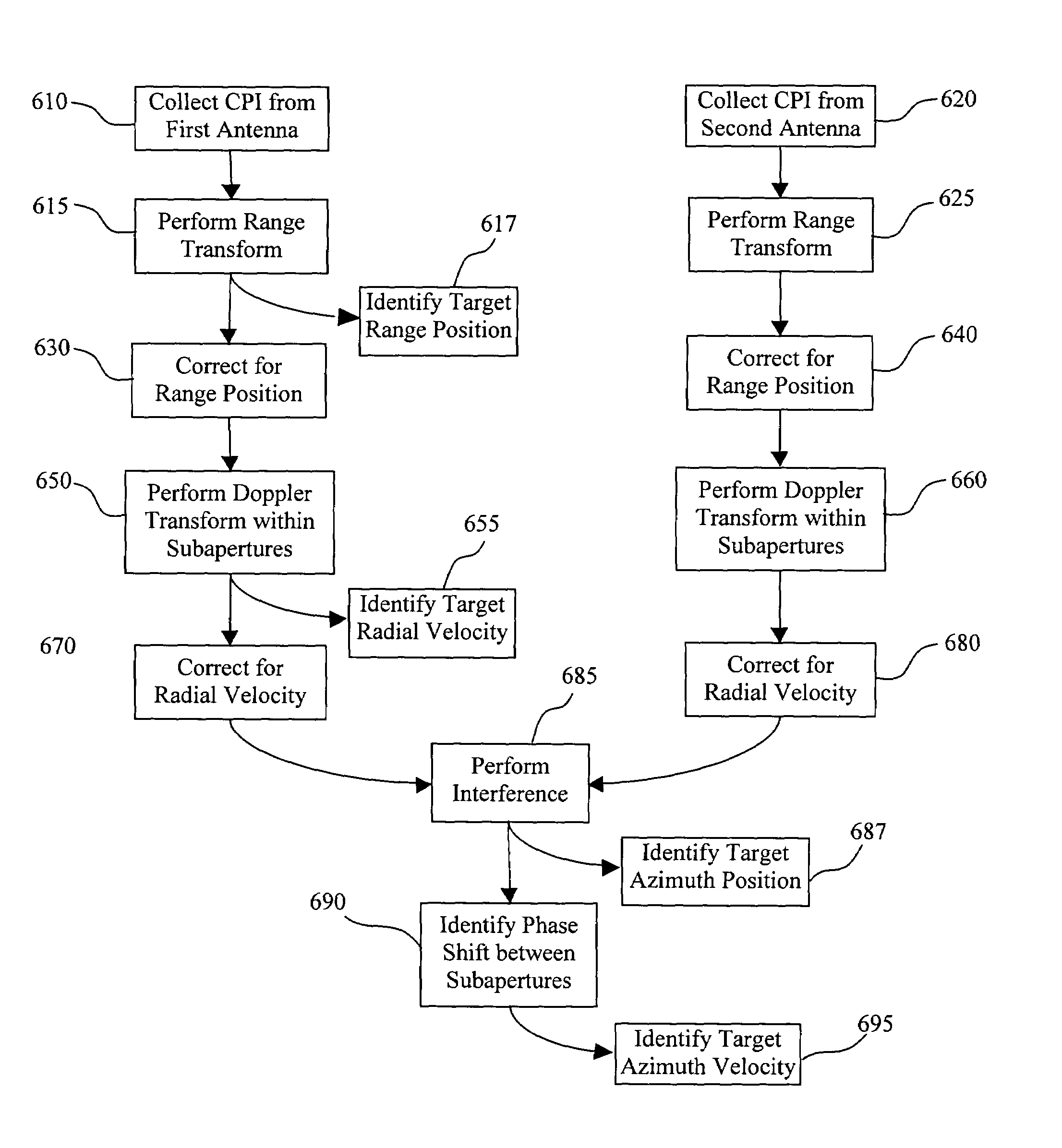
[0011]A radar interferometer can measure angular position to a target with a great deal of precision, even with a single radar pulse. It does so by measuring the phase difference between echoes arriving at the two antennas. A target with tangential velocity will exhibit a pulse-to-pulse change in the angular position as measured by the phase difference between the antennas. This manifests itself as an interferometric phase that changes with time, i.e., a Doppler difference frequency. By measuring this Doppler difference frequency over some Coherent Processing Interval (CPI), a tangential velocity can be calculated for the target. This tangential velocity will be in the direction of the interferometric baseline. Consequently, a multiple orthogonal baseline arrangement can measure tangential velocities in both the azimuth and elevation directions. These coupled with the radial velocity derived from traditional Doppler processing enables a full 3-dimensional velocity vector to be measured from a single CPI.
[0012]According to features of the present invention, subaperture techniques allow for filtering individual Doppler returns when multiple moving targets exist at the same range.
Problems solved by technology
Consequently, a MTI radar generally offers fairly complete position information (angular direction and range) to some degree of precision, but incomplete velocity information since Doppler is proportional to the time-rate-of-change of range, i.e. radial velocity.
Detecting and measuring echo responses from slow-moving target vehicles that are masked by the clutter are considerably more difficult, and are called “endoclutter” GMTI operation.
Although interferometric systems and method provide improved target analysis through clutter reduction, the acquisition of tangential velocity measurements within a single CPI still remains problematic, and has not been adequately addressed in the art.
Method used
View moreImage
Smart ImageViewing Examples

Examples
example
[0061]An interferometric GMTI has an antenna baseline spacing ba=3 m, and an operating frequency of 16.7 GHz. Furthermore, a target exists with an actual tangential velocity of 90 m / s at a range |rc0|=5 km, and SNR after interference is 100 (20 dB). With a CPI of TpN=0.25 s, an expected system precision of σvsa=3.8 m / s can be expected.
The result of the previous example assumes a single CPI. It should be appreciated after the foregoing teaching that tracking the target over multiple CPIs in the conventional manner will allow refinement.
Login to View More PUM
 Abstract
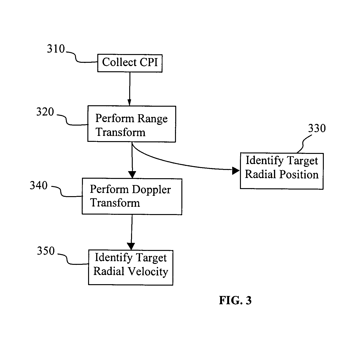
Radar systems use time delay measurements between a transmitted signal and its echo to calculate range to a target. Ranges that change with time cause a Doppler offset in phase and frequency of the echo. Consequently, the closing velocity between target and radar can be measured by measuring the Doppler offset of the echo. The closing velocity is also known as radial velocity, or line-of-sight velocity. Doppler frequency is measured in a pulse-Doppler radar as a linear phase shift over a set of radar pulses during some Coherent Processing Interval (CPI). An Interferometric Moving Target Indicator (MTI) radar can be used to measure the tangential velocity component of a moving target. Multiple baselines, along with the conventional radial velocity measurement, allow estimating the true 3-D velocity of a target.
Description
STATEMENT OF GOVERNMENT INTEREST[0001]The United States Government has rights in this invention pursuant to Department of Energy Contract No. DE-AC04-94AL85000 with Sandia Corporation.FIELD OF THE INVENTION[0002]The present invention is generally related to radar systems. The present invention is also related to methods and systems used to determine a targets range and velocity. More particularly, the present invention is related to use of an interferometric moving target indicator radar to measure the tangential velocity component of a moving target. Multiple baselines, along with the conventional radial velocity measurement, allow estimating the true 3-D velocity vector of a target.BACKGROUND[0003]Although the present background describes the functionality and limitations of synthetic aperture radar systems or a particular class of communications, such description is merely provided to exemplify a problem capable of resolution with the present invention. Any discussion herein dire...
Claims
Login to View More Application Information
Patent Timeline
 IPC IPC(8): G01S13/524
CPCG01S13/589G01S13/5242
InventorDOERRY, ARMIN W.MILESHOSKY, BRIAN P.BICKEL, DOUGLAS L.
OwnerNAT TECH & ENG SOLUTIONS OF SANDIA LLC