
Source driver

a source driver and driver technology, applied in the direction of identification means, pulse techniques, instruments, etc., can solve the problems of increasing the distortion of transmission signals, difficult to supply signals with the expected waveform to each source driver, and difficulty in ensuring wiring regions, so as to reduce the branching of signal lines, suppress and reduce the distortion of signal waveforms

Inactive Publication Date: 2006-01-03
TEXAS INSTR INC
View PDF10 Cites 20 Cited by
  • Summary
  • Abstract
  • Description
  • Claims
  • Application Information

AI Technical Summary

Benefits of technology

[0004]A general object of this invention, which was devised in consideration of this situation, is to provide a display device module that can supply high-speed signals with low distortion and drive large-load signal lines at high speed.
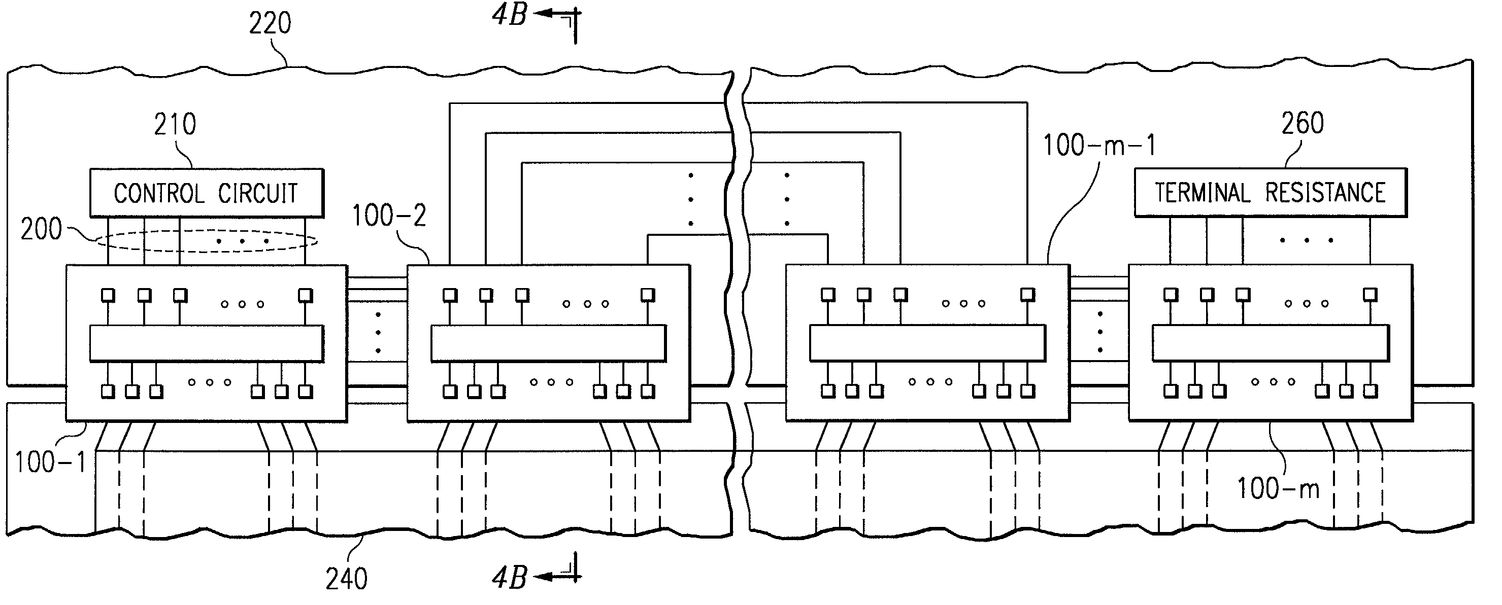
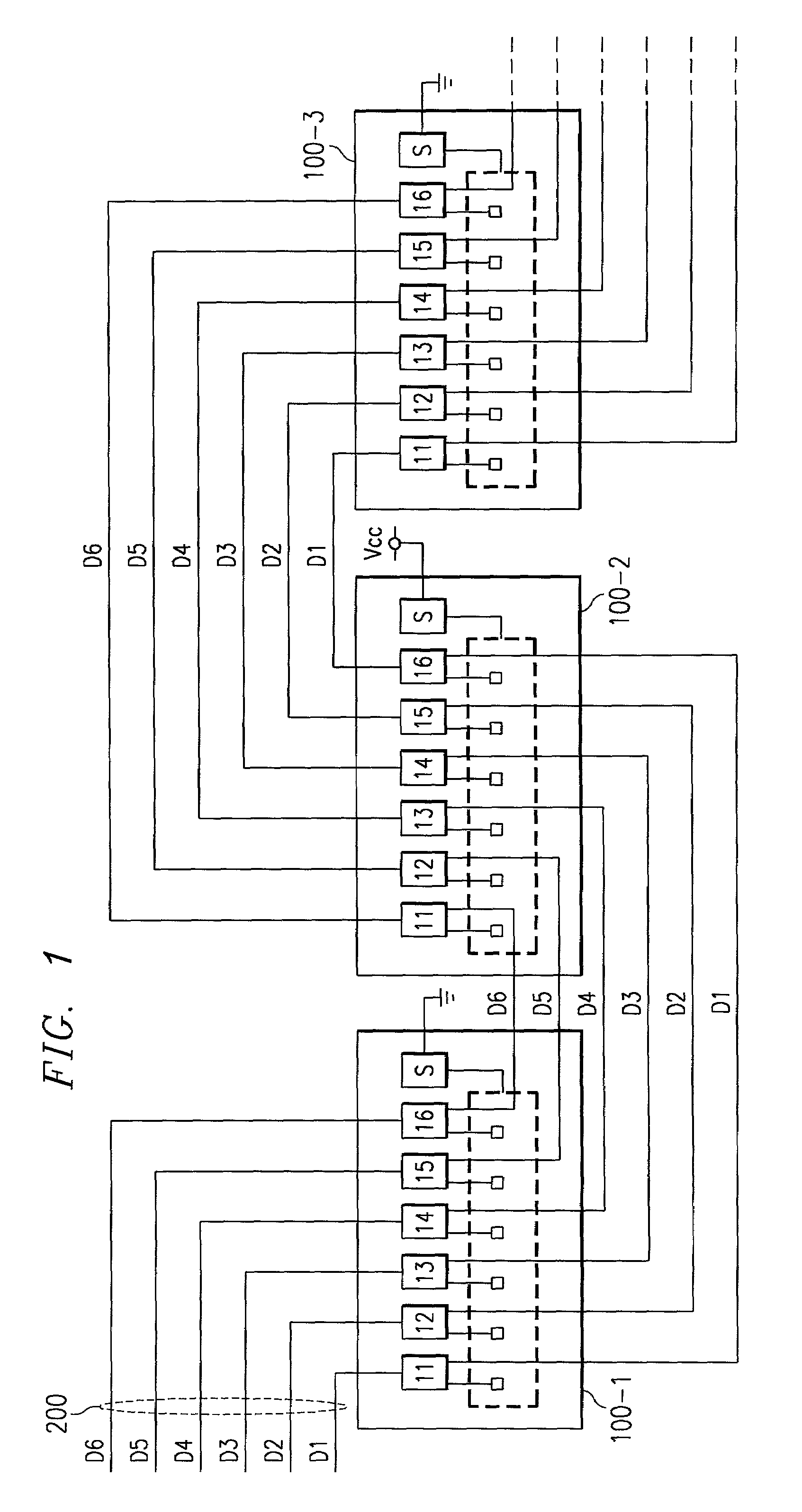
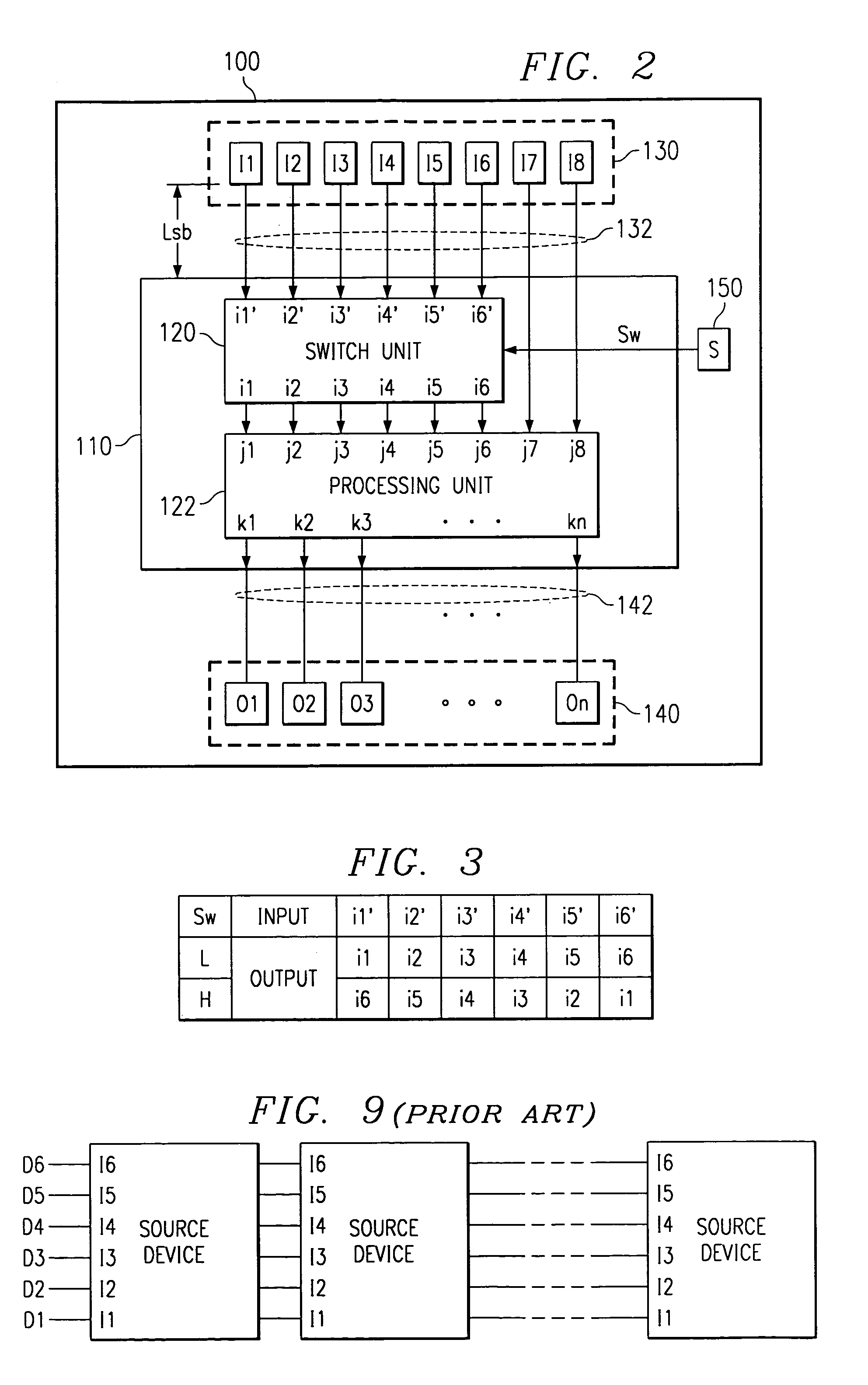
[0006]The drive circuit of one embodiment, provides a switch unit that switches the lineup sequence of multiple input signals inside the drive circuit, the signal lines on the substrate can be wired in a one-stroke-of-the-pen wiring pattern in which they do not intersect each other, and by reducing the branching of signal lines and the effect caused by the reflection of signals, the distortion of signal waveforms can be suppressed. In addition, with this invention, in a source driver that comprises the drive circuit, by forming input pads in pairs and wiring between each pad and an input terminal on the internal circuit, branching of signal lines between the input pad and the input terminal of the internal circuit is eliminated and the reflection of signals is suppressed, with the advantage that distortion of signal waveforms can be reduced.

Problems solved by technology

With conventional drive circuits and their wiring methods there has been the disadvantage that the distortion of the transmission signal becomes greater, and it becomes difficult to supply signals having the expected waveform to each source driver.
But because the source drivers that drive the LCD panel drive about 100–400 signal lines, it is necessary to expand the wiring region of the source drivers, and unlike a memory system, it is difficult to secure wiring region for a vertical arrangement such as that shown in FIG. 9, and normally this cannot be adopted.

Method used


Image

  • Source driver
  • Source driver
  • Source driver

Examples


first embodiment

[0017]FIG. 1 is a circuit diagram showing the first embodiment of the drive circuit of this invention. FIG. 1 shows the arrangement of the source drivers that comprise the drive circuit of the first embodiment of this invention and the wiring method of the data bus that supplies signals to the source drivers. Also shown in FIG. 1 is part of the drive circuit consisting of source drivers 100-1, 100-2, 100-3. In each source driver, for example, digital signals are supplied by six input signal lines. Omitted from the diagram are signal lines that transmit drive signals from each source driver to the LCD panel. An actual drive circuit will have, for example, about 6–12 source drivers, and connected to each source driver are, besides the six digital signal lines that supply digital signals, a clock signal line and control signal lines that supply a clock signal and other control signals, as well as about 100–400 signal lines that are driven by the source drivers. FIG. 2 shows an example ...

second embodiment

[0018]FIG. 5 is a circuit diagram showing the second embodiment of the drive circuit of this invention. As shown here, the drive circuit of this embodiment consists of source drivers 102-1, 102-2, . . . , 102-3 . . . . The source drivers that comprise the drive circuit of this embodiment, like the source drivers of the first embodiment described above, have a switch unit on the integrated circuit formed on the silicon substrate. Said switch unit arranges digital signals D1, D2, . . , D6 input to input pads I11, I21, . . . , I61 into the prescribed order according to switching control signal Sw and supplies them to the processing unit. FIG. 6 shows an example of the composition of a source driver. Labeled here with symbol 102 is a source driver that comprises the drive circuit of this embodiment. Source driver 102 of this embodiment is formed with, for example, silicon substrate 110 sealed by resin on the surface of a flexible wiring board. Also formed on the surface of the flexible ...


PUM

PropertyMeasurementUnit
flexibleaaaaaaaaaa
compositionaaaaaaaaaa
flexibilityaaaaaaaaaa

Abstract

A display device module that can supply high-speed signals with low distortion and drive high-load signal lines at high speed. A switch unit rearranges multiple input signals in accordance with switching control signals and inputs them to an internal circuit, as well as multiple source drivers, are arranged that have an internal processing circuit that generates drive signals based on the prescribed signal processing according to the output signals of the switch unit, switching control signals of different levels are supplied to odd- and even-numbered source drivers, the signal lines that transmit the multiple input signals are wired on the substrate so as to be parallel to each other without intersecting, and the input signals are supplied to the respective source drivers, thus making it possible to shorten the branching lines between the input signal lines and the input terminals of the source drivers, suppress the reflection of signals, and suppress the distortion of signal waveforms.

Description

TECHNICAL FIELD OF THE INVENTION[0001]This invention concerns a drive circuit that drives a liquid-crystal display device (LCD device).BACKGROUND OF THE INVENTION[0002]A liquid-crystal display device consists of a liquid-crystal panel composed of liquid-crystal display elements arranged in a matrix of rows and columns and a drive circuit that outputs drive signals to the liquid-crystal panel. Arranged on the liquid-crystal panel are signal lines that transmits drive signals to each liquid-crystal display element. The drive circuit displays images on the liquid-crystal panel by impressing drive signals that correspond to the display image on the liquid-crystal display elements of the liquid-crystal panel via these signal lines. FIG. 7 shows an example of a general liquid-crystal display device. As shown in the diagram, this liquid-crystal display device consists of control circuit 10, multiple source drivers 20-1, 20-2, . . . , 20-m (where m is a natural number and m>2), data bus ...

Claims


Application Information

Patent Timeline
Patent Type & Authority Patents(United States)
IPC IPC(8): G09G3/36G02F1/1345G02F1/13G09F9/35G09G3/20
CPCG02F1/13452G09G3/3688G09G2310/027
Inventor MATSUZAKI, TOSHIYUKI
Owner TEXAS INSTR INC
Learn More