Unlock instant, AI-driven research and patent intelligence for your innovation.

Technique for fault isolation and transient load isolation for multiple electrical loads connected to a common electrical power source

a technology of transient load and fault isolation, which is applied in the direction of overvoltage protection resistors, emergency protective arrangements for limiting excess voltage/current, and arrangements responsive to excess voltage, etc., can solve problems such as data errors or loss of synchronization on the digital subscriber line, and achieve the effect of preventing substantial power dissipation in the power mos

Inactive Publication Date: 2006-01-03
ADTRAN
View PDF8 Cites 6 Cited by
  • Summary
  • Abstract
  • Description
  • Claims
  • Application Information

AI Technical Summary

Benefits of technology

The present invention provides a power interfacing method and arrangement for a wireline communication network having multiple transceivers connected by way of a common power source. The invention includes current-limiting circuitry and a linear current regulator to isolate faults and prevent voltage spikes that can cause data errors or loss of synchronization. The current-limiting circuitry also regulates the charging current of the remote transceivers to prevent disturbances in the power bus voltage. The invention further includes a feedback control system and ON-timer circuits to ensure stable operation of the power MOSFET and discharge the timing capacitors. The technical effects of the invention include improved fault isolation, reduced power dissipation, and improved stability and synchronization of the network.

Problems solved by technology

A twisted pair fault means an effective shorting together of the two conductors of the electrically powered span, which would cause the central office transceiver to supply electrical current in excess of that for a nominal load condition.
This current transient can be large enough to produce an associated span power bus voltage transient of such a high level that other remote transceivers will not operate properly, resulting in data errors or loss of synchronization on the digital subscriber line.

Method used


Image

  • Technique for fault isolation and transient load isolation for multiple electrical loads connected to a common electrical power source
  • Technique for fault isolation and transient load isolation for multiple electrical loads connected to a common electrical power source
  • Technique for fault isolation and transient load isolation for multiple electrical loads connected to a common electrical power source

Examples


Embodiment Construction

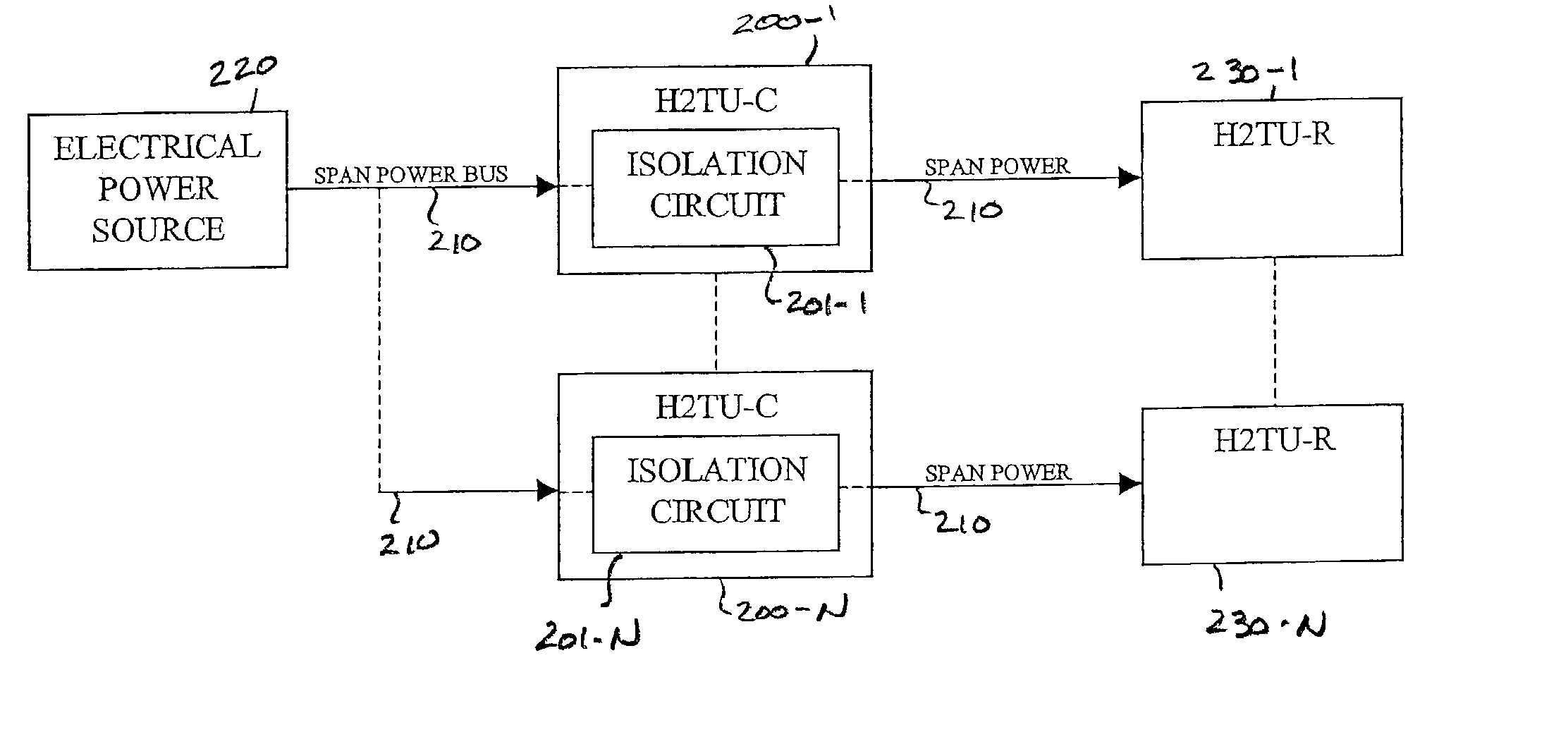
[0020]Before detailing the technique for isolating faults and transient loads for multiple electrical loads connected by way of respective wireline segments to a common electrical power source in accordance with the present invention, it should be observed that the invention resides primarily in a prescribed arrangement of conventional communication circuits and components, and control circuitry that controls the operations of such circuits and components. Consequently, in the drawings, the configuration of such circuits and components, and the manner in which they may be interfaced with various telecommunication circuits have, for the most part, been illustrated by readily understandable block diagrams, which show only those specific details that are pertinent to the present invention, so as not to obscure the disclosure with details which will be readily apparent to those skilled in the art having the benefit of the description herein. Thus, the block diagrams of the Figures are p...


PUM


Abstract

A central office transceiver-installed current limiter and regulator provides fault isolation and transient load isolation in a wireline communication network, having multiple transceivers connected by respective span-powered wirelines to a common power source at the central office. Using a current-sense resistor and controlled switch in series with the wireline, the current-limiter and regulator processes input electrical power from the power source prior to coupling that power to a remote transceiver. To prevent overheating and substantial power dissipation in the current-limiting circuitry in the event of a prolonged fault condition, the controlled switch is alternately turned on and off.

Description

FIELD OF THE INVENTION[0001]The present invention relates in general to electrical power systems and subsystems of the type used for span-powering multiple telecommunication equipments, and is particularly directed to a new and improved fault isolation and transient load isolation scheme for use with multiple electrical loads (transceivers), that are connected by way of respectively different wireline links to a common power source installed at a facility, such as a central office.BACKGROUND OF THE INVENTION[0002]Local Exchange Carriers (LECs) within the telecommunication industry implement a variety of digital transmission systems to service their customers. As diagrammatically illustrated in FIG. 1, a typical digital transmission system may contain a first (network or central office site-associated) transceiver unit 10 that is coupled to a first (e.g., central office) end 21 of a single twisted pair of telephone wires (or span) 20, and a second (remote site-associated) transceiver...

Claims


Application Information

Patent Timeline
Patent Type & Authority Patents(United States)
IPC IPC(8): H01C7/12H02H9/02H04M3/18
CPCH04M3/18H02H9/025
Inventor SMITH, SCOTT L.ROBINSON, STEVEN M.
Owner ADTRAN