Solid electrolytic capacitor

a technology of electrolytic capacitors and solids, which is applied in the direction of electrolytic capacitors, non-metal conductors, conductors, etc., can solve the problems of small degradation of capacitor capacity, inconvenient use of electrolyte solutions, and inability to meet the needs of large-capacity capacitors, etc., and achieves good heat resistance and low esr

Active Publication Date: 2006-01-03
SANYO ELECTRIC CO LTD
View PDF8 Cites 14 Cited by
  • Summary
  • Abstract
  • Description
  • Claims
  • Application Information

AI Technical Summary

Benefits of technology

[0012]An object of the present invention is to provide a solid electrolytic capacitor which solves the above-described problems and has a low ESR and a good heat resistance.
[0016]According to the present invention, a solid electrolytic capacitor having a low ESR and a good heat resistance can be provided by combining at least the tetrahydronaphthalenesulfonate ion and the naphthalenesulfonate ion or the benzenesulfonate ion as dopants.

Problems solved by technology

Though a mica capacitor, a film capacitor, a ceramic capacitor, and the like are used as capacitors for high frequencies, these capacitors are not suitable for large capacities.
Though a large capacity can be attained at low cost with the aluminum electrolytic capacitor, there are problems such as a change of electrolyte solution used over time because of evaporation and a high impedance at a high frequency.
Since the tantalum solid electrolytic capacitor uses solid manganese dioxide as an electrolyte, degradation in capacity of the capacitor is small.
The solid electrolyte of the tantalum solid electrolytic capacitor, however, is formed by impregnation of sintered tantalum with aqueous solution of manganese nitrate followed by pyrolysis of manganese nitrate at about 350° C., which impregnation and pyrolysis steps usually have to be repeated for several to tens times. Therefore, considerable labor is required in formation process of the solid electrolyte.
In addition, since a coating of manganese dioxide is deficient in self-repairing, there is a possibility of ignition or the like when a dielectric coating is damaged while a current is passed therethrough.

Method used


Image

  • Solid electrolytic capacitor
  • Solid electrolytic capacitor
  • Solid electrolytic capacitor

Examples


example 1

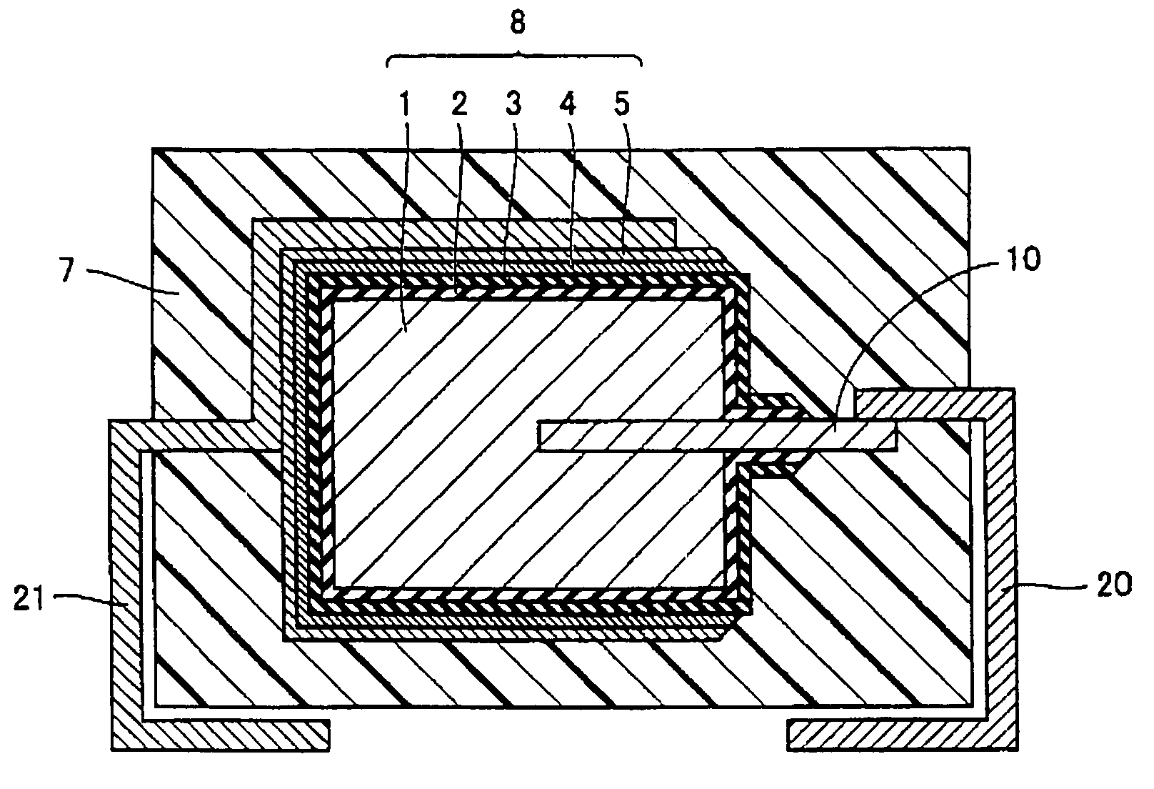
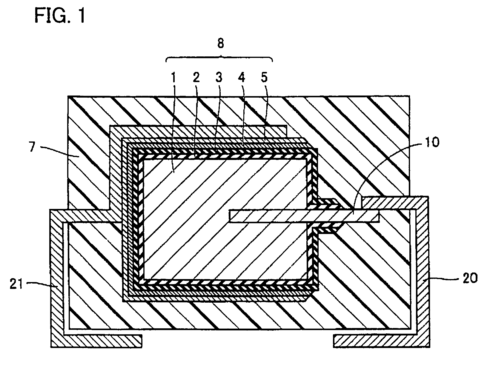
[0033]Referring to FIG. 1, for anode body 1 of a rectangular parallelepiped of 4.36 mm×3.26 mm×0.90 mm formed with sintered tantalum (Ta), having anode lead member 10 inserted thereto from one end surface thereof (a 3.26 mm×0.90 mm surface), anodic oxidation was performed in aqueous solution of phosphoric acid to form dielectric coating 2 on a surface thereof, and electrolytic polymerization was performed using a polymerization solution described below to form solid electrolyte layer 3 on dielectric coating 2. Then, carbon layer 4 and cathode extraction layer 5 were successively formed on solid electrolyte layer 3 to form capacitor element 8. Furthermore, anode terminal 20 was welded to anode lead member 10 and cathode terminal 21 was connected to cathode extraction layer 5 with a conductive adhesive, and thereafter, an outer surface of capacitor element 8 was covered and sealed with exterior resin 7 formed with an epoxy resin to make a solid electrolytic capacitor.

[0034]For forming...

examples 2 and 3

, COMPARATIVE EXAMPLES 1–4

[0036]Solid electrolytic capacitors were formed as described in example 1 except that compounds having molarities as shown in Table 1 were used as polymerization solutions of electrolytic polymerization, and the ESRs before and after the reflow were measured as in example 1. The results are shown in Table 1.

[0037]

TABLE 1ESRESRConductiveBeforeAfterMonomerDopantReflowReflow(Molarity)(Molarity)Dopant (Mol %)(mΩ)(mΩ)Example 1PyrroleBTHNBNBTHN (50)12.213.4(0.2)(0.1)(0.1)BN (50)Example 2PyrroleBTHNMNBTHN (50)16.218.1(0.2)(0.1)(0.1)BN (50)Example 3PyrroleBTHNDBBTHN (50)15.419.2(0.2)(0.1)(0.1)BN (50)ComparativePyrroleBTHN11.721.7Example 1(0.2)(0.2)ComparativePyrroleBN18.820.4Example 2(0.2)(0.2)ComparativePyrroleMN20.122.6Example 3(0.2)(0.2)ComparativePyrroleDB17.225.4Example 4(0.2)(0.2)BTHN: butyltetrahydronaphthalenesulfonate ionBN: butylnaphthalenesulfonate ionMN: methylnaphthalenesulfonate ionDB: dodecylbenzenesulfonate ion

[0038]As shown in a comparative example...

examples 4 – 8

EXAMPLES 4–8

[0040]Solid electrolytic capacitors were formed as described in example 1 except that compounds having molarities as shown in Table 2 were used as polymerization solutions of electrolytic polymerization, and the ESRs before and after the reflow were measured as in example 1. The results are shown in Table 2.

[0041]

TABLE 2ConductiveESR BeforeESR AfterMonomerDopantReflowReflow(Molarity)(Molarity)Dopant (Mol %)(mΩ)(mΩ)Example 4PyrroleBTHNBNBTHN (10)17.519.7(0.2)(0.02)(0.18)BN (90)Example 5PyrroleBTHNBNBTHN (30)15.817.3(0.2)(0.06)(0.14)BN (70)Example 6PyrroleBTHNBNBTHN (50)12.213.4(0.2)(0.1) (0.1) BN (50)Example 7PyrroleBTHNBNBTHN (70)12.114.8(0.2)(0.14)(0.06)BN (30)Example 8PyrroleBTHNBNBTHN (90)11.918.2(0.2)(0.18)(0.02)BN (10)BTHN: butyltetrahydronaphthalenesulfonate ionBN: butylnaphthalenesulfonate ion

[0042]As shown in examples 6 and 7 in Table 2, a solid electrolytic capacitor using BTHN and BN in a mol ratio of 5:5 or 7:3 in dopants maintained low ESRs before and after t...


PUM

PropertyMeasurementUnit
carbon numberaaaaaaaaaa
temperatureaaaaaaaaaa

Abstract

A solid electrolytic capacitor formed with a dielectric coating and a solid electrolyte layer successively formed on a surface of an anode body, wherein the solid electrolyte layer includes a conductive polymer containing at least a tetrahydronaphthalenesulfonate ion and a naphthalenesulfonate ion as dopants or a conductive polymer containing at least a tetrahydronaphthalenesulfonate ion and a benzenesulfonate ion as dopants. As a result, a solid electrolytic capacitor having a low ESR and a good heat resistance is provided.

Description

BACKGROUND OF THE INVENTION[0001]1. Field of the Invention[0002]The present invention relates to a solid electrolytic capacitor using a conductive polymer as a solid electrolyte layer.[0003]2. Description of the Background Art[0004]In connection with size and weight reductions of electric equipment in recent years, a small capacitor of a large capacity for high frequencies, which has a low impedance in a high frequency region, has come to be required.[0005]Though a mica capacitor, a film capacitor, a ceramic capacitor, and the like are used as capacitors for high frequencies, these capacitors are not suitable for large capacities.[0006]On the other hand, an aluminum electrolytic capacitor, a tantalum electrolytic capacitor and the like are suitable for large capacities. Though a large capacity can be attained at low cost with the aluminum electrolytic capacitor, there are problems such as a change of electrolyte solution used over time because of evaporation and a high impedance at ...

Claims


Application Information

Patent Timeline
Patent Type & Authority Patents(United States)
IPC IPC(8): H01G9/00H01G9/028C08G61/12H01G9/042H01G9/15
CPCH01G9/028H01G9/042H01G11/56H01G11/48H01G9/15Y02E60/13
Inventor KAWATA, YOHEITATEZONO, FUMIOOMURA, SEIJIGOTOU, KOUHEI
Owner SANYO ELECTRIC CO LTD
Why Eureka
Try Eureka